
The whole guide on one page
Every chapter one after the other, to print or to save as a PDF: press Ctrl+P and switch off "Headers and footers" in the print settings. To print only a part, choose its page numbers there.
Contents
- Getting started
- View and workplane
- Placing and adjusting shapes
- Selecting and arranging
- Solids and holes
- Breaking edges and hollowing bodies
- Sketches: from outline to body
- Text and curved lettering
- Threads, gears and other parts
- Measuring and notes
- Preparing for 3D printing
- Files, saving and sharing
- Keyboard shortcuts
- Building with an AI (MCP)
- Installing as an app, working offline and self-hosting
- Videos about layerling
1. Getting started
From a blank sheet to your first part for the 3D printer, in five minutes, with no account and nothing to install.
layerling is a design program for 3D printing that runs right in your browser. You build a part from simple shapes, cut holes into it, round the edges and send it to your slicer. There is nothing to install and nothing to sign up for. What you build stays on your computer.
Creating a design
Open layerling.com. On the start page click “Create new 3D design”. The editor opens with an empty workplane, the grid on which everything takes shape.
If you already have a file to continue with, use “Open a design or import geometry”. That works for layerling designs (.lyl) as well as STL, OBJ, 3MF, STEP or SVG files.
All your designs later appear on the start page with a preview picture. They are kept in your browser's storage and saved automatically after every change, so there is no save button. How to pack designs into a file and pass them on is covered in Files and saving.
The editor at a glance

- On top is the ribbon. It is sorted by task: “Clipboard”, “History”, “Shapes”, “Visibility”, “Combine”, “Modify”, “Arrange”, “Manage” and “Help”. Hover over an icon to see its name. Wherever you see a small question mark, for example in a shape's settings, in the shape library or in the tool panels, it leads straight to the matching chapter of this guide.
- In the middle lies the workplane. This is where you place shapes, pull them into form and see the result.
- On the right appear the settings of the selected shape: colour, dimensions, position and whatever else makes up the shape. Typing numbers is more exact than dragging.
- On the left are the camera controls with the view cube above them. They move you around the scene, more in View and workplane.
- At the very top you switch between “3D editor” and “Sketch”, rename the design and choose language and colour scheme.
Your first part
As an example, we build a cube with a hole.
- Click “Add shape” in the ribbon and pick “Box”. The shape now hangs on your mouse pointer. A click on the workplane sets it down.
- On the right, set the dimensions, for example 40 mm long, 40 mm wide and 20 mm high.
- Place a “Cylinder” in the middle the same way, 14 mm across and 30 mm high. It should be taller than the cube so it reaches all the way through.
- Select the cylinder and click “Hole” on the right. It turns see-through: the solid has become a tool that takes material away.
- Select both shapes and click “Group”. The cube now has a hole.
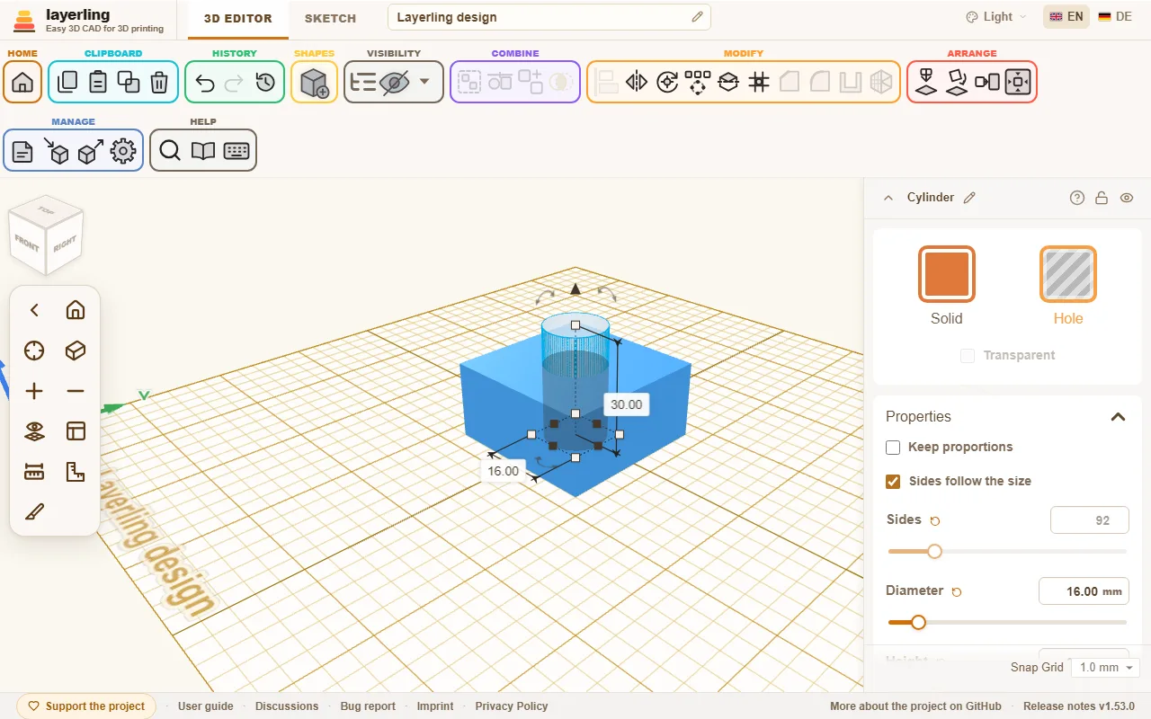
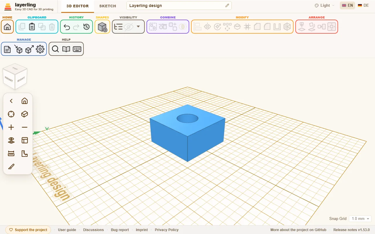
This is how bores, slots and pockets are made. The chapter Solids and holes explains it in detail.
New since your last visit
When you open layerling again after an update, a card on the start page lists what has been added since you were last here: every version since then, the newest first. After a long absence you scroll down inside the card. Below them, “Show earlier versions ({count})” adds the versions from before your last visit too. Close it with “Got it” and it stays away until the next update. “What is new?” in the footer of the start page shows the latest additions again at any time. The browser remembers the last version you saw, and nothing about you leaves it.
On a copy of layerling on your own computer or server, the notice "Update available" has a button, “Preview: what does the update bring?”, that lists what the update brings before you install it. The list is fetched from GitHub only when you press the button.
From design to print
When your part is done, click “Export”, choose STL or 3MF and download the file. Open it in your slicer, for example Bambu Studio, PrusaSlicer, OrcaSlicer or Cura. If you choose your printer in the settings, you can see while building whether the part fits on the print bed. More in Printing.
2. View and workplane
Moving around the scene, looking straight on, and placing new shapes on any surface you like.
Moving around
With the mouse:
| What you do | What happens |
|---|---|
| drag with the right button | rotate the view |
| click the right button | on a body, a menu with the most used commands: duplicate, hole or solid, group, hide, lock, delete and more; on empty space Paste and Select all |
| drag with the middle button | move the view |
| mouse wheel | zoom in and out |
| hold Ctrl and drag with the left button | also moves the view |
On a tablet or phone, two fingers zoom (spread and pinch) and move the view (slide together). One finger works on the design, just like the left mouse button. To rotate with one finger, switch on “Rotate the view with one finger” in the camera bar. That switch only shows on devices with a touch screen.
A graphics tablet with a pen behaves like a mouse: the tip is the left button, the barrel button on the pen the right one, for turning the view and for the menu. The tablet's hotkeys can be set in its driver to layerling's keyboard shortcuts.
The view cube
The cube in the top left shows where you are looking. A click on one of its sides jumps to the straight view from top, bottom, front, back, left or right. A click on a corner of the cube looks at the model diagonally from that corner, and a click near an edge looks from that edge, between two sides; the spot lights up while the pointer is on it. The number keys 1 to 6 give the straight views too. Hold Shift with them and the view also zooms to the selection, as Shift+F does.
Drag the cube to turn the view around, just like dragging with the right mouse button. With nothing selected, the arrow keys turn the view as well: 15° a press, 90° with Shift. They turn the model the way they point - → turns its front to the right, ↑ tilts its front upwards. If something is selected, the arrows move it; click on empty space first to turn the view. On a touch screen this works with one finger, without switching on “Rotate the view with one finger”.
The camera bar
At the left edge is a narrow bar. From the top:
- “Home” brings the whole scene back into view. The key is F or Home.
- “Center view on selection” zooms to the selection (Shift+F).
- “Zoom in” and “Zoom out” zoom step by step, as do the keys + and −.
- “Orthographic view” switches to a flat view in which parallel edges stay parallel. For measuring and lining up edges that is often more comfortable than the perspective view. O switches back and forth, and a second click returns.
- “Hide workplane” (the eye over a grid) hides the plate with its grid, so you can look at the underside of a design from below. Only the view changes: new shapes still land on the workplane. A second click shows it again.
- “Place workplane”, the tape measure and the framing square are tools of their own, covered below and in Measuring and notes.
The small arrow at the very top of the bar hides it if it gets in the way.
A design opens the way you left it: the angle, zoom and position of the view are kept with it in this browser, so you continue where you stopped, also after going Home or closing the page. A saved file (.lyl) carries the view along, so it opens in it elsewhere too. The view is not part of the undo history.
Looking inside: the section view
“Section view”, the last button in the bar (the cut tool), cuts the view open along a plane so you can check walls, cavities and parts that fit into each other. Nothing is cut for real: the design, its files and every export stay whole.
- Choose the axis the plane stands across: X (width), Y (depth) or Z (height), as in the position fields. The plane starts in the middle of your design.
- “Coarse” moves the plane across the whole design, “Fine” moves it a little either side of where it stands, for tenths of a millimetre. You can also type the position.
- The button beside the axes shows the other side of the cut, “Center” puts the plane back in the middle, and “Show cutting plane” hides the blue plane.
- You can click and select what the cut lays open, inner walls included.
- “Workplane here” puts the workplane on the cut. It lies on the plane of the section and faces out of the body that stays, like the face a cut leaves. If you then switch to the sketch, it starts exactly there, and the faint outline shows the cut, which you can draw along and snap to. That is how you sketch a lid that fits the cavity you opened with the section, for example. The button beside the axes chooses which side stays, and with it which way the workplane faces. You put the workplane back on the base plate as usual.
- “Measure” measures right on the cut: the outline shows in blue, and two clicks on it give the distance, plus its parts along the plane's two axes. Both points snap to the outline, corners first. When the second click lands anywhere on the opposite wall, it snaps square to the first point - so you read wall thickness, gaps and clearance without aiming exactly. A third click starts the next measurement, Esc ends measuring. Moving the plane clears the measurement.
- “Section as SVG” saves the outlines on the cutting plane as an SVG at 1:1, for a laser, a plotter, a template or a gasket. An X cut is seen from the right, a Y cut from the front, a Z cut from above. As in the export, only visible bodies go in, holes are already taken off, and bodies of the same colour are joined into one outline. Each colour stays its own path without a fill, so laser software keeps them apart as layers.
The panel hangs on its button. If it covers something, drag it by its title bar anywhere on the workplane; it opens there next time too. Double-click the title bar or drop it at the button to put it back.
Esc closes the panel; the cut stays until you switch it off or go back to the design overview. While it is on, its button stays highlighted. Anything you place on the side that is cut away only shows once you switch the cut off.
The workplane
New shapes align with the workplane. At first that is the base plate with the grid. But you can put it on any surface, to place something on a side or a sloped face.
- Press W or click “Place workplane”.
- Move the mouse over a face of a body. It lights up.
- A click puts the workplane there. Everything you add now sits on that face.
Click on the empty plate instead, and the workplane lies flat at the spot you clicked, on the snap grid. New shapes and a finished sketch, a revolved one too, then appear there rather than in the middle of the plate. While the workplane lies flat on the plate like this, the plate shows only its outline: two grids in the same plane would make a flickering pattern.
On a face the origin of the workplane otherwise snaps to the grid. Click close to a corner of the face and it sits exactly on that corner. Close to an edge it lies on the edge, and the grid lines up with it; that is how you choose the angle of the grid on purpose. Without a corner or an edge, the grid on a lying face runs parallel to the body, so on a turned box it is turned with it.
A click beside the plate or Esc returns the workplane to the base plate. Quicker still is “Workplane back to the base plate”: the button with the downward arrow sits in the camera bar below the eye while the workplane lies on a face. Shift+W puts it directly on the currently selected face. If you hold Shift while clicking, the plane points the other way.
While a workplane sits on a face, an eye appears next to “Place workplane”. It hides the workplane without dropping it, for a clear look at the design: new shapes still land on that face, and rotating still turns about it. A click on the eye shows it again, and so does setting a new workplane.
Grid and snapping
The grid shows the size of the plate. At the bottom right is the snap step: moving and scaling snap in steps of that size, for example 1 mm. Make it smaller for fine work and larger for rough arranging. “Snap to grid” in the ribbon moves the selected shapes afterwards onto the nearest grid crossing. While moving, shapes also snap to other shapes, see Selecting and arranging.
Under “Measurement” in the settings you set the “Units”. With “Imperial”, layerling shows every measure in inches, on the shape, in the properties panel, on the tape measure and the ruler. The snap grid then offers steps from 1/64 to 1 inch, and the grid on the plate is drawn in inches (1/8 to 1 inch, 1/4 inch by default) with a stronger line on every whole inch. Under “Show inches as” you choose whether inches appear as fractions like in Tinkercad (1 5/8, rounded to 1/64 inch) or as decimals (1.625) with as many decimal places as set under “Accuracy”. You can type either, "1 5/8" included.
Under “Custom snap grids” in the same place you add snap steps of your own: a name and a size in millimetres, for example "Pin pitch 2.54 mm" for the spacing of DIP chips, pin headers and perfboard holes, or "MX Key Unit" with 19.05 mm for the spacing of keyboard keys. The snap step menu then offers that measure whole, halved and quartered (1 ×, ½ × and ¼ ×), so shapes can be moved by one pitch, half a pitch or a quarter pitch. Custom steps are kept with the design and go along with “Make default”.
Size, grid width and colour of the plate are changed in the settings (the cogwheel in the ribbon): the areas are “Appearance”, “Measurement”, “Workplane”, “Shape defaults” and “History”. Under “Appearance” you find switches such as “Start editor in perspective view” and “Show shadows”, under “Workplane” “Show grid”. The colours of the work area are set under “Appearance” too: “Window background (light theme)” and “Workplane under the grid (light theme)” for the light theme (the dark themes keep their own), next to the grid colour under “Workplane”. There you also choose whether the darker grid line comes every 5 or every 10 grid steps (“Darker grid line every”) and give it a colour of its own with “Darker line color”; the centre cross and the plate border take it too. Every line of the grid grows wider as you zoom in, as in Tinkercad, and stays visible as you zoom out; if that is too much for you, switch off “Grid lines grow when zooming” and the lines stay one pixel wide at every zoom, as in the sketch. In the colour field, Enter takes a typed hex value. “Edge lines on all bodies” draws an outline on every body, in the colour of “Edge line color” (black to begin with, as in Tinkercad): it helps when dark colours run into each other. It is off by default, and very large imported meshes are left out. The grid always runs through the origin, so the stronger lines lie on the axes whatever the plate measures.
“Axis arrows” (on by default) draws three arrows at the back left corner of the plate: X in red to the right, Y in green to the back and Z in blue upwards, the way the position fields count. That is the right-hand rule Tinkercad, CAD programs and the slicers use too. With the workplane on a face they follow it. Switch them off here if they are in your way.
Two sliders under “Appearance” set how the bodies are lit. “Shadow strength” says how dark the cast shadows are, and “Shading contrast” moves light from the even ambient light to the main light: towards "punchy" the shaded sides get darker and the shadows show more, towards "soft" everything gets flatter. At the top end the contrast gets very strong, so shaded sides and shadows turn really dark. “Shadow softness” makes the edges of the shadows soft instead of crisp. “Light direction” turns the main light round the plate (0° from the front, 90° from the right), and “Light height” lifts it; at 90° it stands straight above the plate as in Tinkercad, and the shadows fall right under the bodies. “Reset light and shadows” puts everything back. “Classic look” sets the work area up as Tinkercad shows it: white ground, a pale blue millimetre grid with a darker line every centimetre, black edge lines, light from above with soft shadows. Every value can still be changed on its own afterwards. All of them start as layerling always looked, and what suits you depends on your monitor. The sketch view has its own colours: “Sketch: window background (light theme)” for the window round the sheet, “Sketch: area under the grid (light theme)” for the sheet under the grid, and “Sketch: grid color (light theme)”, all for the light theme. “Sketch like work area” takes over the work area's three colours in one click.
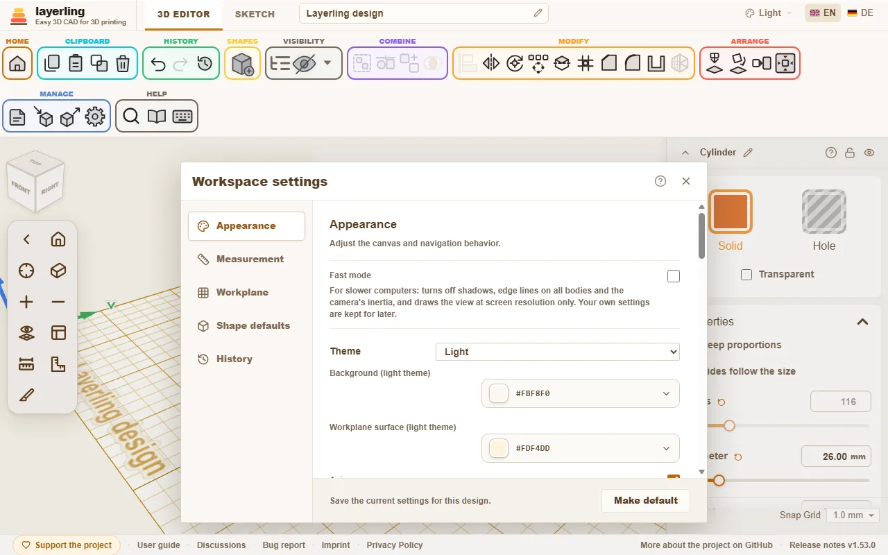
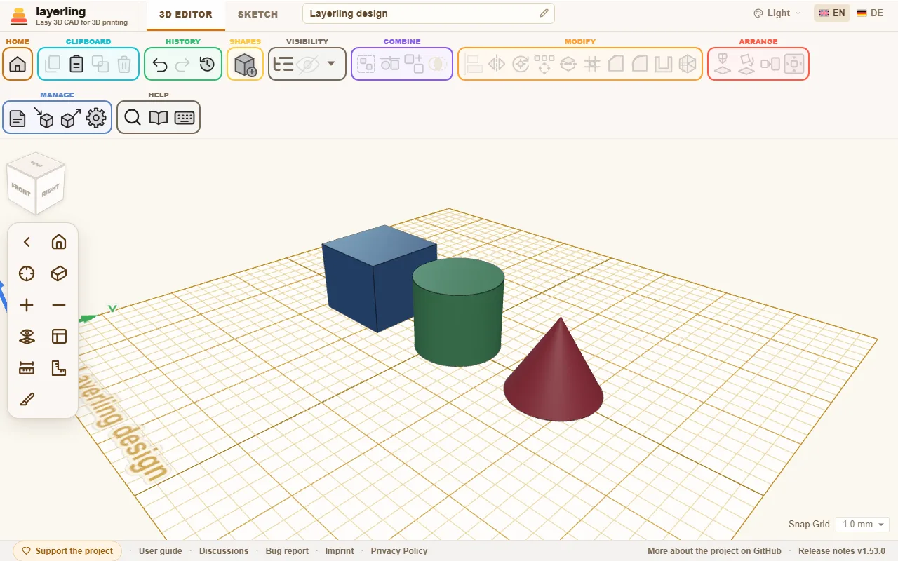
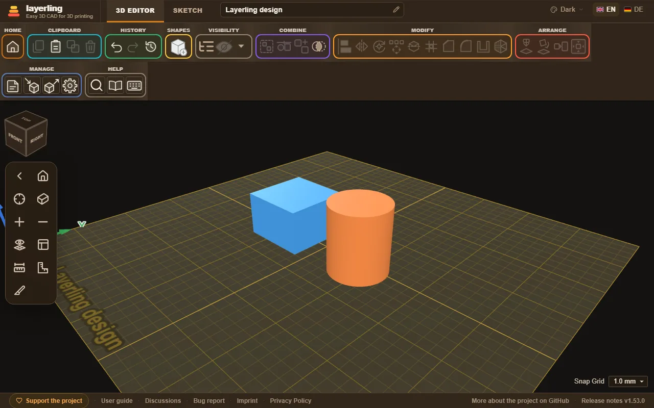
“Toolbar size” under “Appearance” makes the buttons of the ribbon on top, its shape menu and the camera controls on the left smaller or larger: “Small”, “Medium” (as it always was) or “Large”. Small leaves more room for the workplane on a laptop; large is easier to hit on a big screen or with a finger. With large buttons the groups of the ribbon go onto a second row when the window is too narrow for them. The size is kept in this browser and holds for every design.
When layerling feels slow
layerling calculates and draws everything in your browser. On an older computer, with a weak graphics card or on several large screens the view can therefore feel sluggish. This helps:
- “Fast mode” under “Appearance” turns off at once everything that costs the view a lot: shadows, edge lines on all bodies and the camera's inertia. It also draws the view at the screen's own resolution only, which on high-resolution screens is up to four times fewer pixels. Your own settings are kept and apply again as soon as you turn it off.
- The camera keeps turning: When you let go of the mouse after turning, the view turns on for a moment and slows down gently. That is on purpose, not stutter. If you are used to Tinkercad or Fusion 360, turn off “Camera keeps turning” under “Appearance”, and the view stops at once.
- Single switches: Without fast mode you can also turn off just “Show shadows” or “Edge lines on all bodies”.
- Use the graphics card: In Chrome open
chrome://gpu(in Edgeedge://gpu). Next to "WebGL" it should say "Hardware accelerated". If it says "Software only", hardware acceleration is off in the browser's settings. On Windows you can also pick "High performance" for the browser under Settings → System → Display → Graphics, so it uses the real graphics card and not the weaker one in the processor. - Simplify large imported meshes: A model of many hundred thousand triangles slows any view down. How to thin it out is in the chapter on files, under "Simplifying an imported mesh".
- Close other tabs: Every open layerling tab and every other 3D page shares the same graphics card.
3. Placing and adjusting shapes
The shape library, dimensions by number and by handle, colour, rotating, tapering and twisting.
Every part in layerling starts with a shape. From them you build everything else: shapes complement each other, cut each other out or are joined into a new shape.
Adding a shape
Click “Add shape” in the ribbon. The shape library opens.

Pick a shape. It now hangs on the mouse pointer and lands where you click. Move it over a body and it lies down on the face under the pointer, sloped ones too, like Cruise in Tinkercad; over the empty plate it lands on the workplane. Esc cancels placing. A tool that waits for a click, such as the tape measure, the framing square, a note, “Place workplane”, “Lay flat on face” or the edge tools, is switched off when you pick a shape, so the click places the shape. The other way round, switching one of those tools on puts the shape down again. If you would rather have the shape appear in the middle of the plate, you can switch off placing by click in the settings (area “Appearance”, switch “Cruise when adding new shapes”).
What the library offers:
- Basic shapes: “Box”, “Rounded Box”, “Cylinder”, “Capsule”, “Ellipse”, “Polygon” (three to twenty-four sides), “Sphere”, “Cone”, “Pyramid” (with three to twenty-four sides, so three-sided too), “Wedge”, “Round Roof”, “Half Sphere” and “Torus”.
- Tubes: “Tube” and “Bent Tube”, made of up to twelve straight pieces with bends in between, and the “Loft” from one outline to another, say from square to round.
- Decorative shapes: “Star”, “Heart” and “Crescent”.
- Lettering: “Text”, also along a circular arc. More in Text.
- Mechanics: “Thread” (threaded rod, screw, nut and tapped hole), “Spring”, “Gear” and the “Knurl” for grips. More in Threads and mechanics.
- For constructions: the print-in-place “Hinge”, “Dovetail”, the “Teardrop hole” for horizontal holes, the “Counterbore” and “Countersink” for screw heads and the “Ruler”, which is only a measuring tool and never shows up in an export.
You get a triangle in two ways: the “Polygon” with three sides is an isosceles triangle, the "Roof" of Tinkercad, and the “Wedge” is a right triangle. Both are true triangular prisms. For a triangular hole, copy the shape, make the copy smaller, mark it as a hole and line it up with “Center on workplane” or “Align”. Both work with the shape's bounding box, the smallest box that encloses it, so a halved square still counts as a whole square. The command search (Ctrl+K) also finds both shapes under "triangle" or "roof".
The “Capsule” can be narrower at one end than at the other, say for a guard over a belt between two pulleys. Under “Properties” set “Small End (Diameter)”; the large end is as wide as the capsule, and the sides run straight from one arc to the other. “Centre Distance” is the distance between the two arcs' centres, that is how far apart the pulleys are. Change the small end and the centre distance stays, the capsule getting longer or shorter. The tapered capsule stays an exact body too, for fillets and STEP.
The shape's settings
As soon as a shape is selected, its settings appear on the right. At the top is the name; the pencil beside it (“Rename”) lets you type a new one. Enter keeps it, Esc cancels, and an empty name brings back the shape's default name. Further right, the padlock locks the shape against accidental moving and the eye hides it. The arrow on the far left folds the settings down to their title bar.
The settings sit docked at the right edge. If they cover something you want to see, drag them by their title bar and they float wherever you drop them; they stay there for the next shape too. Drop them back at the top right, or double-click the title bar, and they dock again. While they float or are folded down, the snap step moves from the bottom of the settings to the bottom right of the workplane.
- “Solid” or “Hole”: A solid stays, a hole takes material away. A click on “Solid” opens the colours; colours of your own that you mix there wait under “Recently used” afterwards, the last eight. More in Solids and holes.
- “Transparent”: Lets you see through the body, for example to spot a shape behind it.
- “Multicolor”: For a group only. Switched on, every part of the group shows in its own colour, also in a group that was cut with holes into one body (the walls a hole leaves take the colour of the body they were cut into). Picking a colour for the group switches it off and colours the whole group. Bundles always keep their parts' colours. In a 3MF export every part keeps its colour, so the slicer can map the parts onto filaments; OBJ carries the colours on its points, so the border between two colours is a little rougher there.
- “Properties”: The dimensions and everything that belongs to this shape. For a cylinder the diameter, the height and the number of sides. For a gear the teeth, for a spring the turns. A value you have moved away from its default gets a small arrow next to its name: a click takes just that value back, whatever else you did since, unlike Undo. Dragged with the mouse, the slider of a length snaps to the snap step, so a height comes out in whole millimetres (not with the grid off, and not on short sliders); a typed value and the arrow keys on the slider stay exact. “Save as default” at the bottom makes the current values the start values of this kind of shape (the same as “Shape defaults” in the settings), and “Reset defaults” goes back to the app's own.
- “Taper”: Different sizes at the top and bottom, for example for a slope or a funnel.
- “Twist & Lean”: Twists the top against the bottom or shifts it sideways. That gives twisted columns and leaning towers.
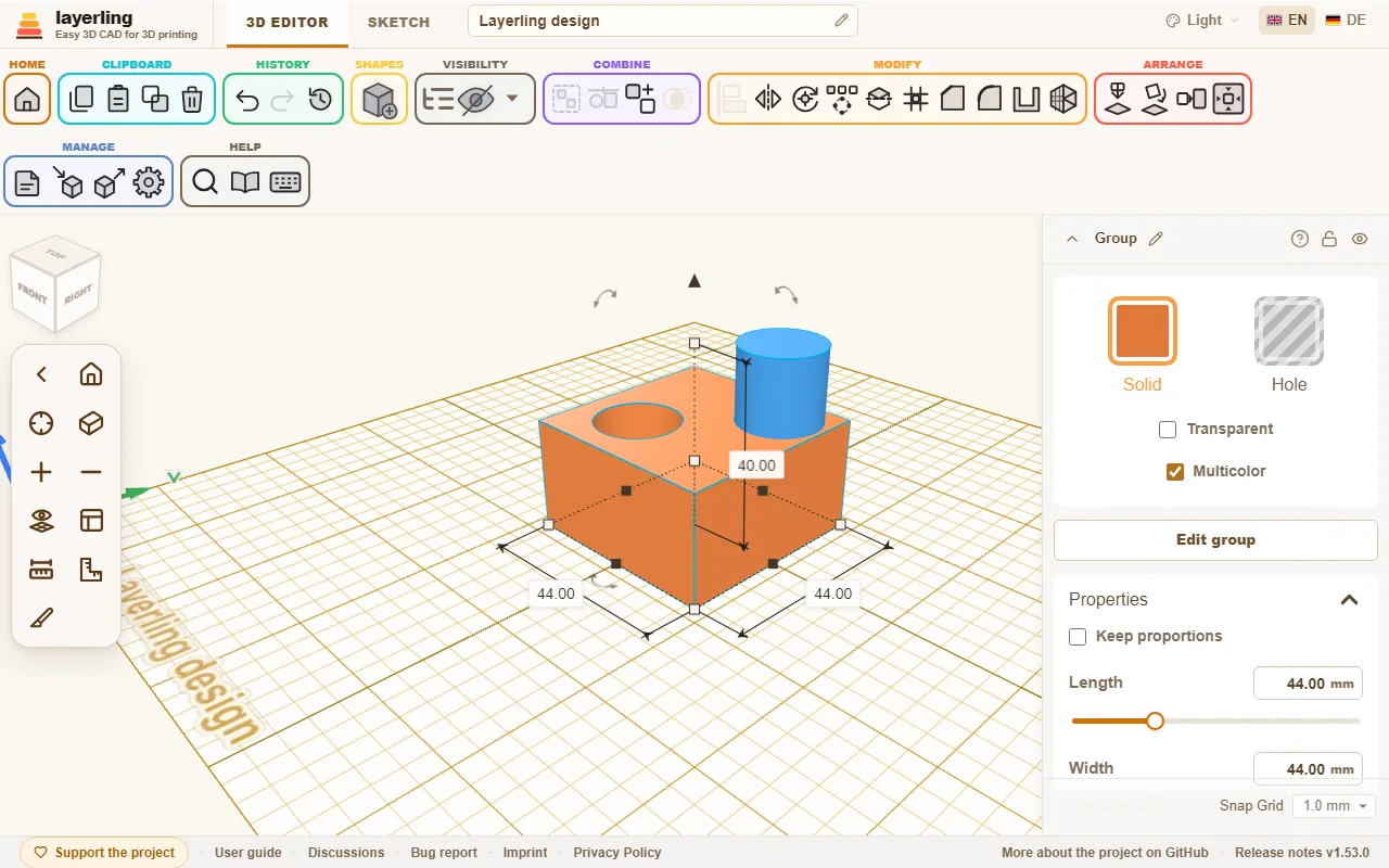
Taper and twist work on almost every shape. Only the gear, thread, spring, knurl, hinge, pyramid, bent tube, teardrop, the screw-head cutters and the ruler leave them out: they have fixed measures of their own or, like the pyramid, a top of their own already.
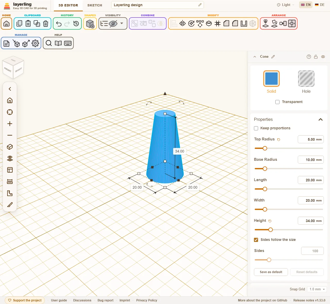
A tapered or leaning box, cylinder, ellipse, polygon, tube or ring keeps its exact shape, and so do the capsule, star, heart, crescent, dovetail and a rounded box without rounded top and bottom edges: chamfers and fillets work on it as on the plain shape, and the STEP export writes it. The same holds for a twisted shape: its section turns exactly as it rises, and the sides wind evenly from bottom to top.
Typing is more exact than dragging. All number fields take millimetres, but also percentages: type "50 %" into a width of 40 mm and you get 20 mm. They calculate too: "15*3", "120-2*4" or "(40+2)/2" give 45, 112 and 21; x works instead of *. The field remembers the calculation, in the Properties panel as well as in the dimension boxes around the selected body: click into it again later and the formula stands there instead of the number, as long as the value still matches it, and you change it in place, "(140+2)/2" becoming "(40+6)/2". Drag the body by a handle or scale it and the formula no longer fits, so the field shows just the number again.
How round is round? The side count
Round shapes such as cylinder, cone, tube, ellipse or the bores have the switch “Sides follow the size” and the slider “Sides” in their properties. The “Torus” has two sliders: “Ring sides” around the ring and “Tube steps” around the tube. They follow the size there too until you hold them, so a large torus shows no facets. The reason: for the view and for STL, 3MF and OBJ, layerling draws a circle as a polygon of many small sides. The more sides, the smoother it is, and the more triangles it takes.
Where the side count matters
- In the export for the slicer (STL, 3MF, OBJ). A cylinder with few sides arrives there as a polygon.
- When bodies and holes are combined. A bore cut by a hole with few sides is angular in the finished part. That includes screw holes.
- In the view. Many very fine shapes slow the editor down.
Where it does not matter
- For the STEP export. It writes the round shape, not the polygon.
- For chamfers and fillets (“Chamfer”, “Fillet”) as long as the shape stays round. That is the case when you have not set a side count, when the count is at least the shape's default, or when the polygon strays at most 0.05 mm from the circle. The default is 96 sides for cylinder, ellipse, tube and cone, 64 for the “Round Roof”, 24 steps for the “Sphere”, 32 for the “Half Sphere”, 96 sides and 24 steps for the “Torus”, and a “Quality” of 32 for a round “Bent Tube”.
- For a thread, a spring or a helical gear. The edge tool and the STEP export take its exact body; its “Quality” only sets how finely it is drawn.
Where it matters again
- For chamfers and fillets on a shape with few sides. If you set the side count below the default, the edge tool takes the shape as it is drawn: a cylinder with 6 sides stays a hexagonal bar, and the fillet runs round its six edges. That is how you can build, for instance, a nut pocket with rounded corners. For a round shape, leave “Sides follow the size” on.
How to use it
- Leave “Sides follow the size” on. Then layerling picks the side count from the diameter so that the polygon strays at most 0.005 mm from the true circle, far below what a printer resolves. Small shapes get at least 24 sides, large ones more.
- Fewer sides you take when you want a polygon on purpose (but there is the “Polygon” for that) or when the editor gets slow with very many round shapes.
- More sides you hardly ever need. Only on very large round parts, when you see edges in the STL.
- For parts you only treat with edges or hand on as STEP, the side count does not matter.
Working with the handles
Besides the settings there are handles on the shape itself:
- The corners and edges make the shape larger or smaller. Hold Shift while dragging a corner to scale width, depth and height together and keep the proportions; hold Alt to scale from the center instead of the opposite corner. Without a keyboard, or if you do not want to hold a key, switch on “Keep proportions” at the top of the properties: then the corners always keep the proportions, and typing one of width, depth or height scales the other two by the same factor. The setting is remembered.
- The arrow on top changes the height, the handle in the middle lifts or lowers the shape.
- The curved arrows rotate it.
- The numbers beside the shape show the dimensions. A click on one opens a field in which you type the number you want.
- A click on a corner (without dragging) opens width and depth together. Type the first, press Tab for the second and Enter to apply both. Esc cancels.
Once a shape is turned by right angles, for instance laid on its side with “Lay flat on face”, the fields in the properties are named after the direction each measure runs in now: “Height” is what goes up, “Width” runs along X and “Length” along Y. Typing the height of a shape lying down therefore changes the vertical measure, and its underside stays on the plate. A shape tilted at any other angle shows its own measures in the fields, and a note below says so.
Without the mouse, use the keyboard: the arrow keys move the selection by one snap step (0.1 mm when the grid is off), with Shift by five, or by ten if you set “Darker grid line every” to 10 “{count} grid steps” in the settings under “Appearance”: as far as the next darker line, as in Tinkercad. They follow the view: → moves to where the screen's right is, ↑ away from you, even after turning the plate. Push a shape out of the picture and the view moves along. Ctrl+↑ and Ctrl+↓ raise and lower it. R rotates by 45°, Shift+R by 22.5°. D drops the selection onto the workplane.
The handles pull a shape as large as your plate, at least 220 mm wide and deep. Typing a number in the properties goes beyond that, and a shape made that large does not shrink back when you grab it again. A ceiling of your own per shape is set in the settings under “Shape defaults” with “Custom size limit”.
The snap step is at the bottom right of the editor and can be changed at any time.
Copying and duplicating
“Copy”, “Paste” and “Duplicate” are in the ribbon (“Clipboard”). Ctrl+D duplicates a selection. layerling remembers how you last moved or rotated the copy and applies the same again on the next duplicate. That produces a row of holes or steps in a few key presses. For regular arrangements there is also the pattern, described in Selecting and arranging.
Custom shapes
A holder, a grip or a base plate you need again and again goes into the “Custom shapes”. They sit at the top of the shape library, above the “Basic shapes”, and fold away with their arrow.
- Select one or more bodies, holes, groups or an imported model included.
- Open the shape library and click “Save selection”. Enter a name and confirm with “Save”.
- In any design, a click on the tile inserts the shape, like any other shape. You can also drag the tile onto the workplane; it then lands where you let go.
Several bodies come back together, placed as they stood to each other, and stay selectable one by one. The pencil on a tile renames it, the bin removes it after asking. Shapes already inserted into designs stay as they are.
The “Custom shapes” live in this browser, apart from the designs, and are there again the next time you start. “Back up all” on the start page backs them up with the designs, and opening the backup brings both back. To take only the shapes to another browser, “Back up custom shapes” (the arrow pointing down) saves them as a ZIP file and “Load shapes” (the arrow pointing up) brings them back there. “Load shapes” also takes single .lyl designs; each one becomes a shape. Shapes already there are not added twice.
Custom shapes on the server
With the shared server store switched on, the section shows two groups: “On the server” and “In this browser”. When saving you choose where the shape goes; the server is chosen to start with. There it lives in the folder Custom shapes, as a .lyl file of its own with a picture, ready on every device that reaches the server. The cloud on a browser tile puts that shape on the server; it is then no longer kept twice.
The Custom shapes folder shows on the start page as well. Open a shape there like a design, change it, and it is saved automatically like any design on the server; the next insert takes the new version. As the server store has no login, everyone who reaches the server sees the same shapes.
Wrapping around a cylinder
Should a pattern, a logo or lettering go onto a cup, a can or a tube? First lay it flat on the plate, as an imported SVG or as text for example, the way it should look from above. Then wrap it around a cylinder in the shape's settings under “Wrap around a cylinder”:
- Open “Wrap around a cylinder” and enter the “Diameter” of the cylinder wall, such as the outside diameter of your cup. Tenths of a millimetre work too, such as 63.5.
- Click “Wrap”. What ran from left to right now runs around the cylinder, the back edge becomes the top, and the thickness stands out of the wall.
- Select the wrapped shape and the cylinder and centre both, left to right and front to back. The middle of the wrapped shape is the cylinder's axis, so it then sits right on its wall.
For an engraving, switch on “Inward (engraving)”: the thickness then goes into the wall. Make the shape a hole, centre it and group it with the cylinder.
The result is a mesh like an imported model. Undo lays the shape flat again; for another diameter, undo first and wrap again. It cannot go further than once around the cylinder; then layerling names the smallest diameter that fits.
4. Selecting and arranging
Selecting shapes, finding them in the object list, aligning, mirroring, rotating, laying flat on a face and multiplying in patterns.
Selecting
A click on a shape selects it. With Shift you add more or take them away again. A click on empty space clears the selection, and so does Esc. Drag a frame on the empty workplane to select everything it touches; with Shift held, the frame adds what was not selected and takes away what was. And Ctrl+A selects all visible bodies.
What is in your way you hide (“Hide selected”, Ctrl+H). Hidden shapes stay in the design, they are just not visible and stay out of the export; the export window says beforehand how many there are. Ctrl+Shift+H brings them all back. What should stay put you lock with the padlock at the top of the settings or with Ctrl+L. A locked shape cannot be moved, resized, turned, recoloured or deleted: its handles turn grey, a padlock shows beside the arrow on top, and the tools that would change it are greyed out. Hovering a handle still shows its sizes, and a key that would change it says "Object locked". While one locked shape is in the selection, nothing changes for the others either. Hiding, renaming, copying and duplicating still work.
The object list
With many parts it is easy to lose track in the view. The object list (“Show object list” or Ctrl+Shift+O) shows all shapes as a list.
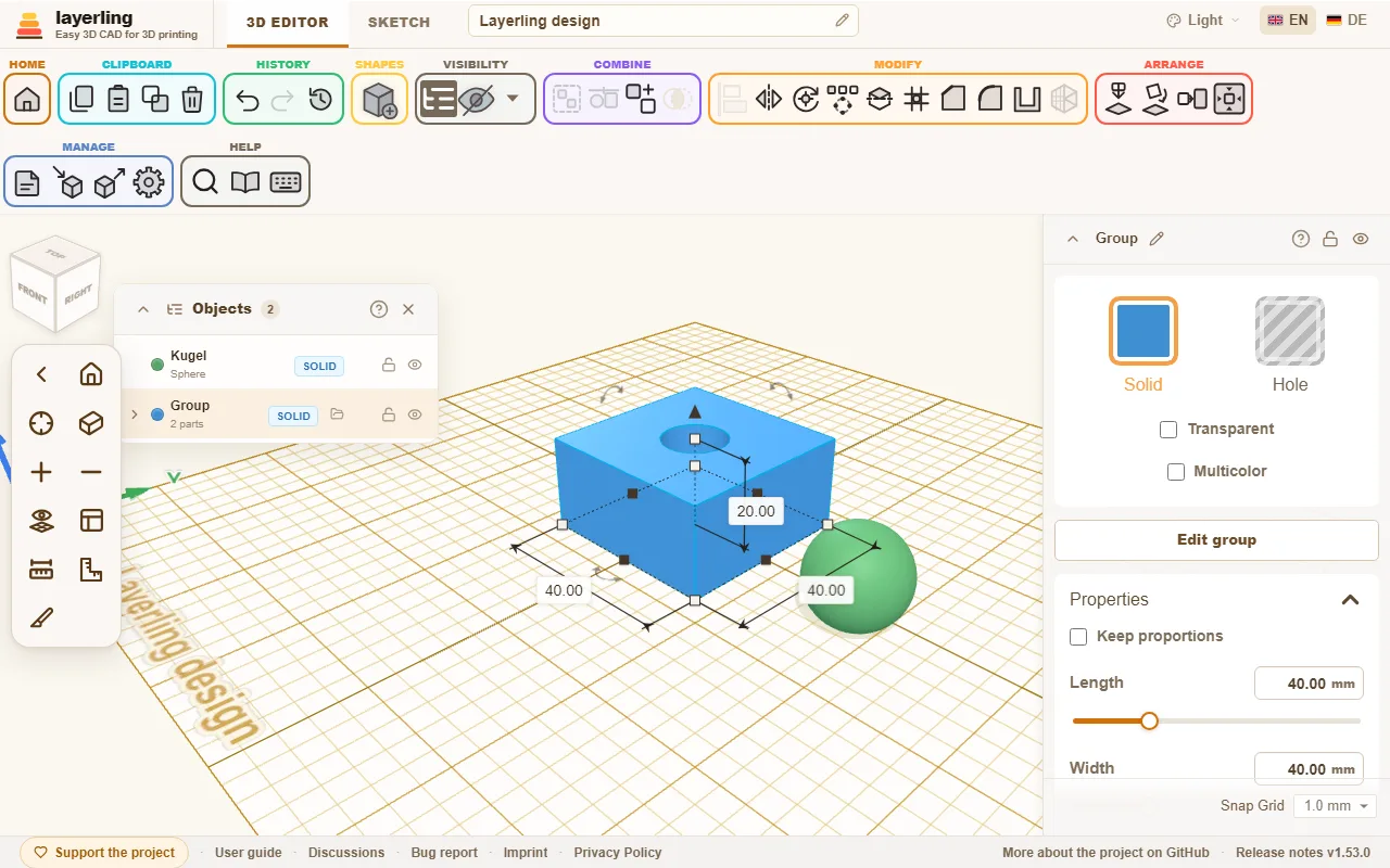
- A click on an entry selects the shape, including parts inside a group. With Shift held you add more entries or take them away again, just as in the view. The arrows fold groups open and shut.
- The label shows whether a part is “Solid” or “Hole”.
- Padlock and eye lock and hide single parts.
- “Rename” gives a part a name of its own; the pencil beside the name at the top of the settings does the same for the selected shape. Sensible names help enormously in larger designs.
- The search field finds shapes by name and by kind, so also "cylinder" or "hole". It also looks inside groups, however deeply nested: a group holding a match stays in the list and folds open to show the matching parts and the groups that lead to them. A group found by its own name shows all its parts when you open it.
- The arrow on the far left of the title bar folds the list down to its title bar and back.
The list sits docked just right of the view cube. Drag it by its title bar to put it anywhere on the workplane; it passes underneath the view cube and the camera bar. Drop it back beside the view cube, or double-click the title bar, and it docks again. Where it was and whether it was folded are remembered in this browser.
Typing a position
The card “Position” in the properties panel shows where the selected body stands, and you can type it: “X” and “Y” are the middle of its box on the plate, with the same signs as the distances shown on the workplane, and “Z (height)” is the height of its underside. X counts to the right, Y towards the back and Z up, by the right-hand rule as in Tinkercad and CAD programs; the axis arrows on the plate show the directions. The values go in the unit you set, and the sliders reach as far as dragging does.
Parking parts beside the plate
You can drag a shape past the edge of the plate and leave it there, about one plate width beyond each side, to keep it for later. The arrow keys move it as far as you like. A parked part still belongs to the design and goes into the export with everything else. To leave it out, hide it or export only the selection. If you have picked a printer, layerling warns at export when something sits outside its plate.
Snapping while moving
When you drag a shape across the workplane, it snaps to other shapes: its left, right, front or back edge or its centre lands exactly on an edge or centre of another shape. A pink guide line shows what it is holding on to. That way two parts sit flush side by side or centred one behind the other without typing numbers. It works with the grid switched off, too.
Hold Shift while dragging to keep the move on one axis: the shape follows whichever direction, X or Y, you have dragged further in, and leaves the other alone. Best press Shift once you are already dragging; on a shape that is not selected yet, a click with Shift only adds it to the selection.
With Alt already held when the drag begins, you drag a copy, as in Tinkercad: the shape stays where it is and the copy lands where you let go. Pressing Alt only on the way pauses snapping; the shape then follows the grid only. A copy, too, snaps only once you let go of Alt on the way. To switch snapping off for good, use the grid menu in the bottom right (“Snap to shapes”) or the settings. For now only moving on the normal workplane snaps, not lifting and not resizing.
Aligning
Two or more selected shapes are lined up with “Align”: points appear around the selection for left, centre and right, front, centre and back, and top, centre and bottom. A click on a point moves all shapes there. If you first click one of the selected shapes, it stays in place and the others line up with it. A locked shape in the selection is that fixed shape by itself. Left, right, front, back, top and bottom go by the box round a shape; the centre of a triangle, a pentagon or a star is its own middle, so a hole centred on one sits in the middle of the shape and not of its box.
A shape turned at an angle, say by 45°, has its box round it to line up with, not its own edges. To line up with the edges, set a workplane on a face of that shape first (“Place workplane”, then click the face): the points then stand on the axes of that plane, and the shapes are measured and moved along them, as in Tinkercad. Reset the workplane to line up along the plate again.
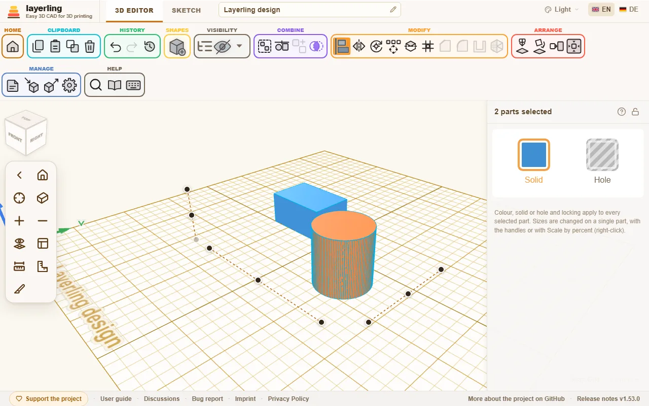
The key is L. Esc cancels.
Mirroring
“Mirror” (M, or right-click the selection and choose it) flips the selection across a plane: “left-right”, “front-back” or “top-bottom”. Click the matching axis arrow. That is handy for symmetric parts: build one half, copy it and mirror the copy.
Rotating and setting the pivot
You rotate with the curved arrows on the shape, with the numbers in the settings or with R in 45° steps. When you drag on the rotation circle, the turn snaps to every tick, that is every 22.5°; hold Shift for finer steps, and extra ticks appear every 11.25°. Drag outside the circle to turn freely in 1° steps, or in 45° steps with Shift. Normally the selection turns about its centre. Sometimes it should not, for example when a tilted tube is to be turned further at its end. For that there is “Set rotation pivot”: afterwards click on a face. A flat face supplies its centre, for example the axis of a tube end. The selection now turns about that point. A second click on the tool removes it again.
The angles stay with the body. In its settings, “Rotation” shows them as “About X”, “About Y” and “About Z (height)”, named like the position: Y runs across the plate, Z is up. Type an angle there and the body turns to it - about its centre, or about its own pivot if it has one. While a turned body is selected, its angles also show below it on the workplane; “Show the angles of turned bodies” in the settings switches that off.
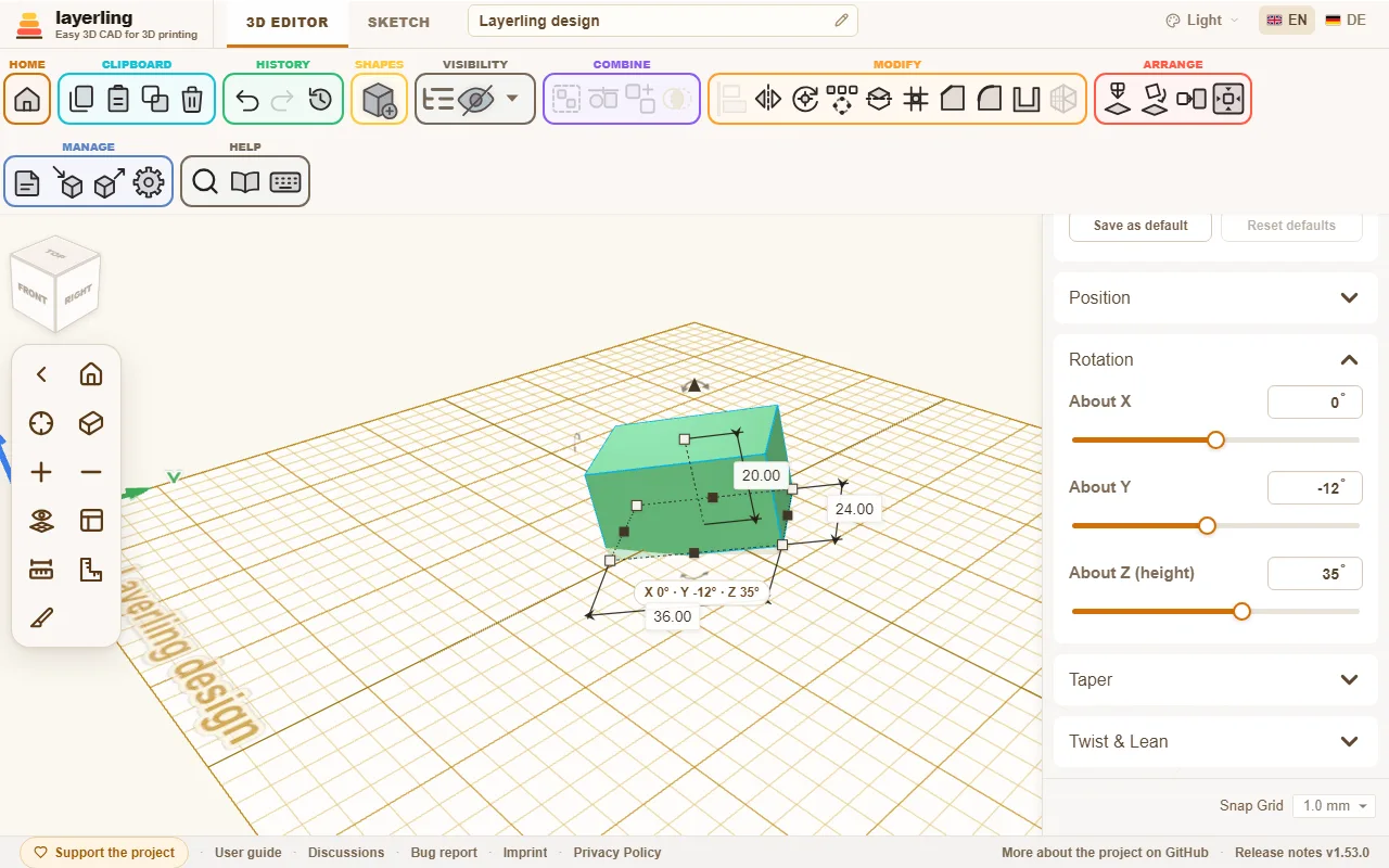
With one body selected, the pivot belongs to that body: select other parts and come back, and it is still there. It moves, turns and scales with the body, is saved in the project and comes back with Undo. Under “Position” the pivot has its own X, Y and Z, which you can type or nudge, and “Remove” takes it away. You can also drag the pivot's red marker with the mouse: it slides over the surface of the bodies and snaps to corners, edge midpoints and edges, so a hinge pin lands exactly on a corner. With several bodies selected the pivot is only for that selection, and a new selection removes it.
Laying flat on a face
Should a part lie on its best side for printing? Select it, click “Lay flat on face” and then the face that should go down. While you move the pointer over the part, the face under it lights up, so you see which one you are about to pick; turn the view to check the other sides. The part turns so that this face rests on the workplane.
Two parts should meet face to face, or line up flush? Select the part that should move, click “Align faces”, then click its face and after that the face of the other part. In the panel, “Face to face” puts the faces against each other (back to back, touching), “Flush” lays them in one plane side by side; “Gap” leaves room between them, for example for clearance. “Align” moves the part: it turns the shortest way until the faces are parallel - not at all if they already are - and then slides only towards the other face, so it keeps its place sideways. The other part stays where it is, and one Undo takes it all back.
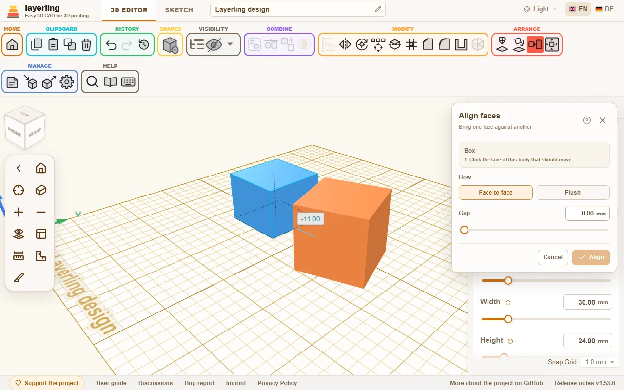
Just as simple are “Drop to workplane” (D), which drops the selection onto the workplane, and “Center on workplane”.
C picks the selection up, like Cruise in Tinkercad: it follows the mouse pointer and lies down on the face of another body you are over, sloped ones too. A click sets it down there, Esc leaves it where it was. Its underside then rests on the face, lined up with the face's edges as a new shape would be; it keeps its own turn about its up axis. Several parts travel together and keep their spacing. Over the empty plate, C stands a tilted part upright on the workplane again.
Patterns: row and circle
For hole grids, bolt circles and rings of teeth there is the “Pattern”. Select the shapes to be multiplied and click it in the ribbon.
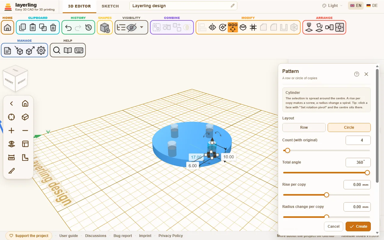
- “Row”: The selection is repeated at equal distances. The row steps along all three axes at once, with “Spacing X”, “Spacing Y” and “Spacing Z (height)”: one of them gives a straight row, two or three a diagonal row or a staircase. A negative spacing lays the row the other way.
- “Circle”: The selection is spread around a centre. How many copies there are you set under “Count (with original)”, and the “Total angle” is 360° for a full circle. Choose whether the copies turn along. “Rise per copy” lifts every copy a little more than the one before (a screw or an ascending spiral), and “Radius change per copy” moves it further from the centre or closer to it (a flat spiral); together they give a conical spiral.
Tip: first set the pivot on a face with “Set rotation pivot”, then the centre of the circle lies exactly there.
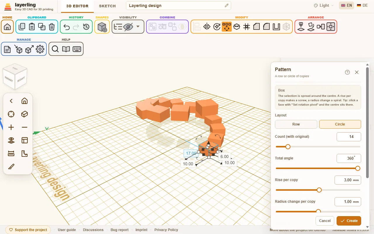
The copies first appear as a preview. Only “Create” creates them. If the copies are holes, group them afterwards with the body they should cut into.
Hole pattern on a face
For vents, speaker grilles, baskets and enclosures the “Hole pattern” spreads holes evenly over a flat face. You no longer have to make one hole, repeat it and set it onto the wall. Select exactly one body and click “Hole pattern” in the “Modify” group of the toolbar, next to the pattern. You can also right-click the body, or find it with Ctrl+K.
- Click a flat face of the body. The whole flat face around your click counts, not just the triangle under the pointer. A curved face does not work: you get a hint and click a flat one instead.
- In the window, set how the holes look and lie:
- “Hole shape”: “Round”, “Square”, “Rectangle”, “Hexagon” or “Slot”.
- Size: the “Diameter (Ø)” of a round hole, the “Side length” of a square one, “Width” and “Height” for a rectangle and a slot. For the hexagon the size is the “Diameter across the corners (Ø)”.
- “Spacing centre to centre”: the distance from one hole's middle to the next. If it is smaller than the holes allow, layerling raises it to the smallest possible value so a wall stays between the holes.
- “Wall between the holes”: the same distance said another way: the wall left between two neighbouring holes, which is the wall thickness in the print. Set it and the spacing centre to centre follows, and the other way round. For hexagons, rectangles and slots layerling measures the least distance between their edges.
- “Arrangement”: “Grid” puts the holes in rows and columns. “Staggered” shifts every second row by half a spacing and moves the rows closer, so every hole has neighbours at the same distance - with hexagons that makes a honeycomb.
- “Margin to the face's edge”: the clear distance between the holes and the edge of the face. Only holes that lie wholly inside the face minus this margin are made; anything that would reach beyond it is left out. The margin also holds around openings in the face.
- “Depth”: “Through the whole body” (the default) cuts through the whole wall. With “Custom depth” you give the depth in millimetres, for recesses, say.
- The holes show at once as a preview on the face and follow every value. The window says how many holes fit. “Another face” chooses another face, Esc closes the tool, and like the other tool windows it moves by its title bar.
- Only “Create” makes the holes.
The holes are ordinary holes grouped with the body, just as after “Group”: nothing is baked in. “Ungroup” dissolves the group again and frees every hole, which you can then move, change or delete one by one. The whole thing is one step for “Undo”. The tool does not make more than 400 holes at once; make the holes bigger or the spacing wider then.
An AI can do the same through the MCP bridge with layerling_perforate_face (see the chapter AI with MCP).
Changing several parts at once
With several parts selected, the properties panel on the right shows how many there are and offers what applies to all of them together: “Solid” or “Hole”, one colour for all (a click on “Solid” opens the colours) and the lock. With a mixed selection, one click makes them all solids or all holes. If any of the parts is locked, only the lock can be used. Sizes are changed with the handles, with “Scale by percent” or by typing a number into a size label. With several parts the number is the size of the whole selection: every part grows with it, the spaces between them too, as when you drag a handle. Solid and hole also work with a right-click or the S and H keys.
Scaling by percent
To make one or several parts larger or smaller by the same share, say all the parts of a print file by 20 %, use “Scale by percent”. Select the parts, right-click them and choose “Scale by percent”, or search for it with Ctrl+K.
Under “New size” you type the new size as a percentage of the current one: 120 % is a fifth larger, 50 % half the size. Width, depth and height change alike, so the proportions stay. The bottom stays where it is, so nothing sinks into the plate.
With several parts you choose how they grow:
- “Together”: The parts grow around their common centre, and the gaps grow with them. The whole becomes larger as if it were one part.
- “Each in place”: Every part grows where it stands, and the gaps between them stay the same.
Only “Scale” changes the design, and one step back undoes it. With a locked part in the selection it does not open.
Undoing
“Undo” (Ctrl+Z) and “Redo” (Ctrl+Shift+Z or Ctrl+Y) step through your history. How many steps travel with the saved design you set in the settings under “History”.
Looking back: the history view
“History”, next to undo and redo, opens a view of your history without changing anything. The work area shows the design as it was, and a slider at the bottom runs through every undo step: all the way to the right is the current state, each step to the left is one undo earlier, and states you have undone sit to the right of the current one. The arrow keys step through the states, Esc returns to the current state. You can turn and zoom the view meanwhile, but nothing can be selected or moved; the design itself stays exactly as it is. If the bar covers something, drag it away by its title bar; a double-click on it brings it back.
Two things you can take along from an earlier state. “New project from this state” puts that state into a new design in the overview, named after this one with the time of that state in brackets - a design saved before layerling recorded times says "copy" instead - and with the history up to that point, so undo keeps working there. “Export this state” opens the usual export with that state as the design, so you can save it as STL, 3MF, STEP, a picture or a LYL file with the history up to that state.
“Delete history” sits alone at the bottom left of the bar. After a question it removes every earlier step for good: the design keeps the state it has now (not the one shown), Undo has nothing to go back to and a file saved afterwards carries no history. Use it to share a design without its past, or to start the undo steps over. It cannot be undone; to share a file without touching your own design, choose “None” when exporting instead.
5. Solids and holes
How simple shapes become bores, slots and pockets, and how to change a group again later.
This is the most important idea in layerling, and it is quickly learned: Every shape is either a solid or a hole. A solid stays. A hole is a tool that takes material away.
Solid or hole
Select a shape and click “Solid” or “Hole” in its settings. The keyboard is faster: H makes the selection a hole, S makes it a solid again. Both are also in the menu a right click on the body opens. A hole is shown see-through so you can see where it sits. T makes a body see-through, say to look into a housing; a second press makes it opaque again. It works on the whole selection: if any body is already see-through, all become opaque, otherwise all become see-through.
As long as nothing is grouped, nothing happens with a hole. It just lies there and shows where something will disappear later.
Grouping
Select solids and hole(s) and click “Group” (Ctrl+G). Now the holes remove the material from the solids they touch. What remains is one single new shape.
This is how you get:
- Bores: a cylinder as a hole through a body.
- Slots: an elongated box as a hole at the edge.
- Pockets: a hole that does not go all the way through.
- Threads in a part: a tapped hole as a hole, see Threads and mechanics.
If several solids are in the group, they are joined. Two solids that touch become a single part.
You can treat a group like a shape: move, rotate, colour, group again. “Ungroup” (Ctrl+Shift+G) dissolves it and the individual parts are back.
Making a group a hole
A whole group can also be a solid or a hole. A simple rule applies:
- If the group consists only of solids (or only of holes), you switch it as a whole and its parts go along.
- If it contains both, say a cube with a bore, each part keeps its own state. The whole group then becomes a tool, but the bore stays a bore.
Bundling
Sometimes parts should only stay together without becoming one - a white logo on a black plate for a multicolour print, say. That is what “Bundle” (Ctrl+B) is for, as in Tinkercad. A bundle moves, turns and resizes like a shape, but nothing is merged:
- Every part keeps its colour and stays a solid or a hole.
- Holes cut nothing.
- In an STL, 3MF or OBJ export every part is a body of its own; in 3MF and OBJ with its colour.
“Ungroup” (Ctrl+Shift+G) takes a bundle apart again, E opens it for editing like a group. Chamfer, fillet and hollowing do not work on a bundle, because it is not one body: group it for that, or work on its parts one by one. If a hole in the bundle should cut after all, group the bundle (Ctrl+G).
Intersection
“Boolean Intersection” keeps only what two or more bodies have in common. Lay two overlapping shapes on top of each other, select both and click it. That turns a cylinder and a box into a piece with one round and one straight side. A group counts the way it looks, holes included. If a hole is selected too, what remains is what all the solids share with all the holes.
Editing a group
If a bore turned out too small, you do not have to dissolve the group and rebuild. Select the group and click “Edit group” in its settings, the folder icon in the object list, or press E. A double click on the group does the same, as in Tinkercad, on a bundle too; if you would rather not, switch off “Double-click opens a group or bundle” in the settings. A part only starts to move once the pointer has been dragged a few pixels, so a shaky click or double click does not nudge it. The parts now lie separately and you change them with every tool: make a hole larger, move a body, add a hole.
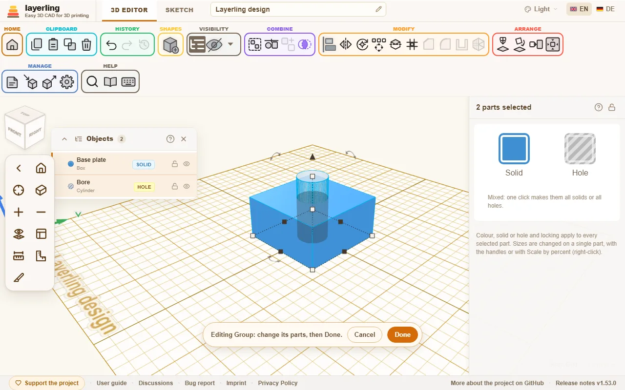
A bar appears at the bottom of the picture. “Done” rebuilds the group, with its name, its colour and its state as solid or hole. “Cancel” puts it back untouched.
If one of the parts is itself a group, you can edit it the same way, and so on as deep as your design goes. The bar shows where you are, for example "Bracket › Screw boss". “Done” and “Cancel” always finish the innermost group and take you one level back out. While you are inside a group, only the groups among its parts can be edited; to edit another one, finish first.
Unlike “Ungroup”, which takes a group apart for good, editing keeps the group: its name and settings stay, and you can always go back with “Cancel”.
A note: fillets and chamfers you had put on the whole group are lost on rebuild. The bar tells you so.
Splitting
“Split” in the “Modify” area cuts the selection in two with a plane - a part too big for the print bed, say, or one you want to see the inside of. Select one or more solids or holes and click it. A translucent plane shows exactly where the cut will go; nothing changes until you apply it.
- “Plane orientation”: X makes an upright cut between left and right, Y between front and back, Z a horizontal cut between top and bottom. The axes are named as on the Position card, with Z up; Z is where the plane starts.
- “Plane position”: where the plane crosses, with the slider or typed in. It starts in the middle. You can also drag the arrow head on the plane; the plane moves along the arrow in 0.1 mm steps.
- “Pick face”, the button next to the position, lays the plane on a face: click it, then click the face. Orientation, both rotations and position are set to match. While you pick, a blue plane under the pointer shows the face it will take. A face of a body that is not selected works too, to line the cut up with it, but the plane stays within the selection. Esc stops picking and leaves the plane where it was.
- The two rotation sliders below turn the plane about the other two axes, up to 180° either way, for an angled cut. They can be combined.
“Split model” or Enter makes the cut, Esc cancels (while picking a face, the first Esc only stops picking). Every object the plane crosses becomes two closed bodies, named after their side, for example "Box (Z+)" and "Box (Z-)"; objects it misses stay as they are. A hole becomes two holes, and a hollowed body keeps its cavity. Both halves stay where they were - for printing, lay each one on its cut face with “Lay flat on face”.
The halves are plain meshes: settings such as a cylinder's sides or a text's lettering are gone, so set those first. Ctrl+Z brings the original back in one step. Locked and hidden objects cannot be split.
Separating parts
If a shape consists of several separate pieces, such as text made of single letters, “Separate Parts” splits it into independent shapes.
6. Breaking edges and hollowing bodies
Chamfer and fillet on chosen edges, walls of equal thickness for boxes, cups and cases.
Chamfering and filleting edges
Sharp edges rarely look good on a printed part, and they are not particularly strong either. A chamfer cuts the edge off at an angle, a fillet rounds it. Both act on the edges you click.
- Select the body (or the group).
- Click “Fillet” or “Chamfer” in the ribbon, press B for the fillet or Shift+B for the chamfer, or right-click the body and pick it from the menu.
- The body's edges light up. Click those that should be affected. Another click takes an edge out again. With Shift you add or remove a single edge.
- Set the size and confirm with “Apply” or Enter.
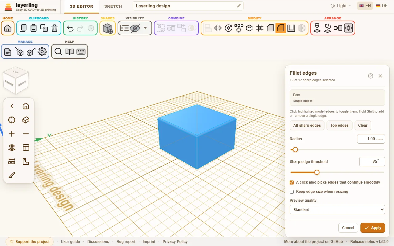
The panel sits at the top right. If it covers edges you want to click, drag it away by its title bar; it opens there next time too, and so do “Hollow” and “Pattern”. Double-click the title bar to put it back.
Picking a shape from the shape list while the panel is open closes it without applying anything, and the edges you clicked are forgotten. The click then places the new shape instead of picking edges.
In the panel you find:
- “All sharp edges” selects every edge at once, “Clear” empties the selection.
- “Radius” for the fillet. For the chamfer you set “Distance” or “Angle”.
- “Sharp-edge threshold” decides which edges count as sharp at all. A value of 25° treats only clear kinks as edges and leaves flat transitions alone.
- “Top edges” picks only the edges along the very top of the body. It is the quick way for a cookie cutter: build the outline in a sketch as a stroke, then chamfer the top edges. “Angle” sets how steep the chamfer is; it cannot reach further than the wall is thick.
- “Only visible edges” hides the edges that lie behind the body from where you look. By default every edge shows through the body, which gets confusing on a busy part; with the switch on you see, and can click, only the edges facing you. Turn the view to reach the others. An edge drawn in red (see below) always shows.
- “A click also picks edges that continue smoothly”: a click then also picks edges that flow smoothly into each other, for example all edges around a face with rounded corners. The switch only decides what a click picks: the CAD kernel always carries a chamfer or fillet on along such smoothly continuing edges. The panel tells you along how many more edges that happens.
- “Keep edge size when resizing” keeps the chamfer or fillet as large as it is, even if you scale the body later.
- “Preview quality” (“Draft”, “Standard” or “Fine”) decides how finely the preview is calculated. For difficult parts “Draft” is faster.
While you adjust the size, layerling recalculates the preview. It can take a moment. You may keep adjusting; the last value you chose is what gets calculated.
If the size is too large for the edge, layerling says so and suggests a smaller value. Often one or two millimetres less will do. At sharp angles a fillet needs more room than its radius suggests. On a small screen the panel scrolls down by itself so the message is in view.
When a selection that worked fails after you click one more edge, that edge turns red and is drawn wider: it is the one that cannot be treated together with the others at this size. Click it again to take it out, or make the size smaller. If you click more edges while the message stands, the first one stays red. When there is no earlier selection that worked - the very first click, or a size you just raised - the edges that fail even on their own turn red, or all of them if it is only their combination.
The edge under the pointer is drawn wider too, so you can see which one a click will pick.
Taking an edge treatment back
A treated body can always be treated again. Select it again and open the tool - Fillet, Chamfer or Hollow, each shows the list: under “Undo an edge feature” you see what is already on it. “Undo” takes back a single treatment. Note: if newer treatments lie on top, they go with it, and the panel tells you how many.
Next to a chamfer, a fillet or a hollowing there is also “Edit”. It takes the treatment back the same way, but opens the tool again at once with the same edges and the old value. You change the value and apply it again: a 3 mm fillet becomes a 5 mm one without clicking the edges once more. If newer treatments lie on top, they go with it here too. This holds for edge treatments you make from now on; older ones only offer taking back, and so do single parts of a group.
On a group, say a cylinder with a hole, the treated edge belongs to the finished body, not to one of its parts. So the group becomes a single body, and “Ungroup” is no longer available. Take the treatment back as described above and the group returns with all its parts. The easiest way is to treat edges last. That goes for threads too: the edge tool takes a thread as its exact body, so a block with a tapped hole in it gets its edges rounded with the thread in place. Working out a thread's edges takes longer than for a plain shape, a few seconds for an M6 and about half a minute for a G1/2 pipe thread.
A part imported as STEP keeps its CAD geometry too: chamfers, fillets and hollowing work on the body from the file, however finely the part is drawn on screen. STL, OBJ and 3MF bring only triangles, and a finely drawn part can be too dense for the edge tool. If a part is also available as STEP, import that.
Hollowing bodies
Boxes, cups, cases and covers have one thing in common: they are empty inside, with walls of equal thickness. That is exactly what “Hollow” does.
- Select the body and click “Hollow”, or right-click the body and pick it from the menu.
- Set the “Wall thickness”.
- Under “Open sides”, switch on the sides that stay open: “Top”, “Bottom”, “Front”, “Back”, “Left” or “Right”, as many as you like - “Front” alone makes a slot for a drawer, “Left” and “Right” a tunnel. With no side switched on the body stays closed all round, with a cavity in the middle.
- Decide whether the “Inner edges” should be “Rounded” or “Sharp”.
- Click “Hollow”.
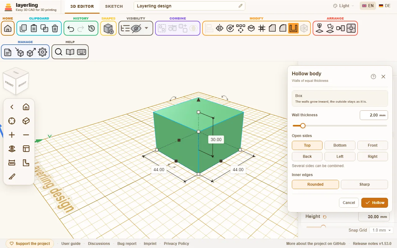
The walls grow inward. The outside stays as it is.
The “Inner edges” only matter where the inner walls move apart - at a step in the body or around an opening. The corners of the cavity of a plain box are always sharp, with both settings. For a rounded inside, round the outside edges of the body first (see above), then hollow it: the inside follows with the radius minus the wall thickness. If the rounded inside cannot be built, which can happen with an outline made of very many short straight pieces such as a traced drawing, layerling builds the same hollow body with sharp inner corners instead.
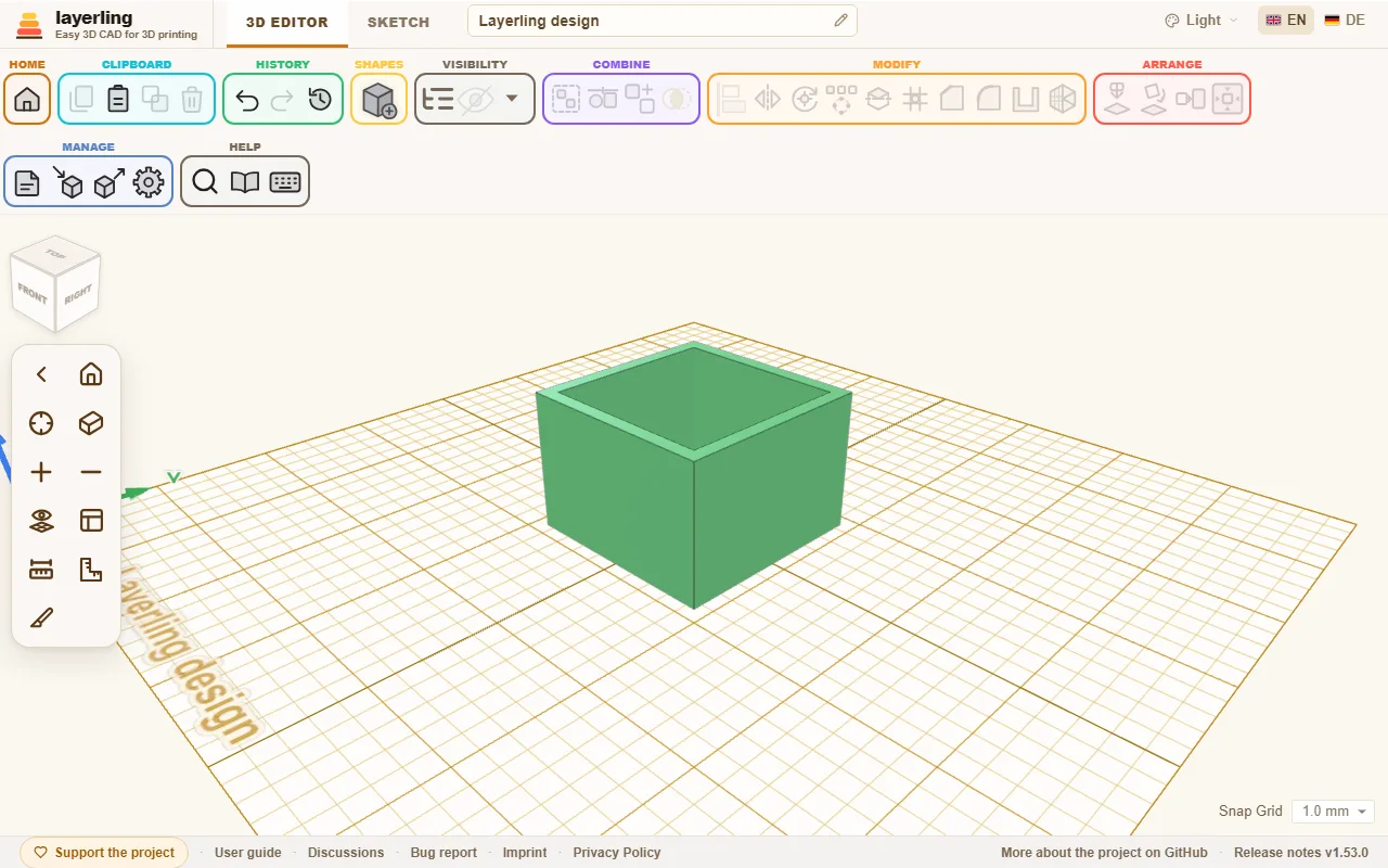
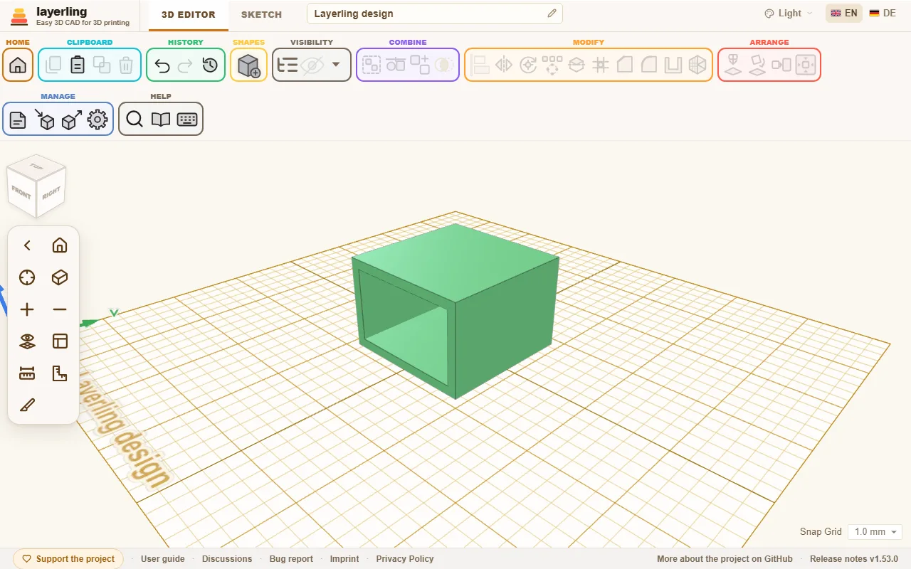
For every open side, the body needs a flat face at its very edge on that side. Spheres and free-form shapes therefore cannot be hollowed this way. If the wall is too thick for the body, layerling tells you and asks for a thinner one.
A body with a pocket - a block with a hole that does not go all the way through, made by grouping a box with a raised hole - can be hollowed too, with the top open: the walls round the pocket are hollowed as well, so a ring of cavity stays between the outer wall and the pocket, open at the top, and a thin cavity lies under the pocket's floor.
Bodies that end in a point, such as a cone or a revolved triangle, have no flat face on top that could stay open. A fully closed cavity does not work there either, because a point cannot be offset inwards: even with a 1 mm wall you get the message that the walls cannot be this thick. Draw the wall into the profile before revolving instead: duplicate the outline, scale the copy down evenly, put it in the middle of the large outline and cut the large one with it, then revolve the whole (chapter Sketches, section Revolve). The distance between the two outlines is the wall thickness.
If you resize a hollowed body later, layerling hollows it again at the new size right away. The wall stays as thick as you chose, round bodies included. A cylinder you pull further one way than the other becomes an ellipse.
7. Sketches: from outline to body
Draw a flat outline, round or chamfer its corners and pull or spin it into a body.
Not everything can be put together from basic shapes. For parts with a contour of their own, such as a bracket, a tooth profile or a vase, you first draw the outline and then make a body from it. That is what sketch mode is for.
Starting a sketch
At the top, switch from “3D editor” to “Sketch”. Click “Sketch to 3D” in the ribbon and choose what the outline should become:
- “Extrude sketch”: The outline is pulled upward, like a cookie cutter.
- “Revolve sketch”: The outline is spun about an axis, as on a lathe. That gives vases, cups, cones and everything round.
The editor then shows a sheet with a grid. That is your drawing surface.
Drawing
The ribbon in sketch mode is divided into areas:
- Draw: “Line” makes straight sections: click points one after another; holding Shift snaps the new line in 15° steps, horizontal and vertical included. The length and angle of the new line show at the pointer. You can also type how long it should be, see Lines by numbers. The “Bezier Curve” is shaped with its handles: click a point and drag in the direction the line should carry on, as with the pen tool in Illustrator or Inkscape. The further you drag, the more it bends; the stretch to the new point bends along while you drag, so you see what you get. Dragging while you place a point bends the curve; if you come from Tinkercad and just want to click points, take the “Smooth Curve”. The “Smooth Curve” lays a flowing path through the points you click. To close the outline, click the first point again at the end.
- Shapes: “Add sketch shape” offers ready-made outlines: “Rectangle”, “Circle”, “Oval”, “Half circle”, “Pie slice”, “Bolt circle” (a disc with holes), “Triangle”, “Hexagon”, a “Polygon” and a “Star”. Click one to put it at the origin of the sketch, or drag it from the menu to where you want it. At the bottom of the menu, “Sides / points” sets the number of sides of the polygon and of points of the star, and “Star inner size” how deep the star's valleys reach in towards the middle (10 to 90 percent of the outer radius); both apply to the next shape you add. Like every sketch shape they are ordinary corner points afterwards, so you can move, round or chamfer them one by one.
- Overlapping: Push two closed outlines over each other and they stay two bodies, which merge in the 3D editor; the overlap is not a hole. A hole only comes from an outline lying wholly inside another. Moving does not join the lines where they cross, so you can pull the shapes apart again. If you draw a line across others, though, layerling puts a point at every crossing.
- Selection: “Select” moves points and lines. A click inside a closed outline selects the whole outline, so you can drag or resize it straight away; inside a hole it picks the hole. The frame around the selection has eight handles: the corners change width and height together, keeping the proportions while you hold Shift. The ones on the sides change one direction only. Click the width or height pill to type a new size, also as a sum ("60+12.5") or in percent ("150%"). With Shift held, a click on a point or line adds it to the selection or takes it away again, so you can pick several and move them together. Drag a box over empty space to select everything in it. A line can be dragged too (it moves by its two ends, or all of the selection if it is part of one). The arrow keys move the selection by one grid step, Shift with them by a larger one, and Shift held while you drag keeps the move on one axis. “Add or Remove Points”: a click on a section adds a point, a click on a point removes it. Also there are “Erase” and inserting a template image (“Add Image”).
- Clipboard: “Copy”, “Paste”, “Duplicate” and “Delete” work on the selected points, lines and images, as in the 3D editor; Ctrl+X cuts. Pasted and duplicated geometry lands next to the original with a 10 mm gap, on a free spot where it touches no existing line, so it never gets joined to what is already there. It stays selected, so you can drag it straight into place.
- History: “Sketch undo” and “Sketch redo”.
- View: Pan it with the middle mouse button or with Shift or Ctrl plus the right mouse button, as in the 3D editor. F fits the whole sketch in the view, Shift+F zooms to the selection, and + and − zoom in and out, as in the 3D editor. The “Tape measure” on the side bar measures the distance between two points. The sketch also shows dimensions as soon as you click something: the length of a line, or for a point the lengths of the lines that meet there. The “Show measurements” button on the side bar hides and shows these dimensions when they get in the way, for example while shaping curves; the tape measure keeps working. On a straight line you can click the dimension pill and type the length in millimetres; Enter applies it, Esc cancels. The line keeps its direction, its start point stays where it is, and the lines at the other end follow. With an end point selected, that one moves. Alt+Enter grows the line to both sides around its middle. On curves the pill only shows the length.
A body comes only from a closed outline.

Lines by numbers
Once you have set the first point with “Line” or “Smooth Curve”, just type a number: two fields open next to the line, “Length” in millimetres and “Angle” in degrees. < or Tab moves to the angle, so "50<30" gives a line 50 mm long at 30°, as in AutoCAD. Enter sets the point, and you can type the next line straight away; Esc closes the fields without ending the line chain.
The angle counts counterclockwise from the right: 0° to the right, 90° up, 180° to the left, 270° down. Leave it empty and the line follows the pointer, so you give only the length and show the direction with the mouse. Sums like "40+12.5" work in both fields. If the point would land off the plate, the field says so and waits for another value.
Curving a straight side
Select a straight line and click “Curve line” in the bar that appears: the side bows out into a curve, as in Tinkercad, and shows its two handles. Drag them to shape the curve; the further out a handle stands, the stronger the bend. “Straight line” makes the side straight again. A point you select can be made round with “Smooth Curve”: it gets handles of its own and the lines next to it become curves.
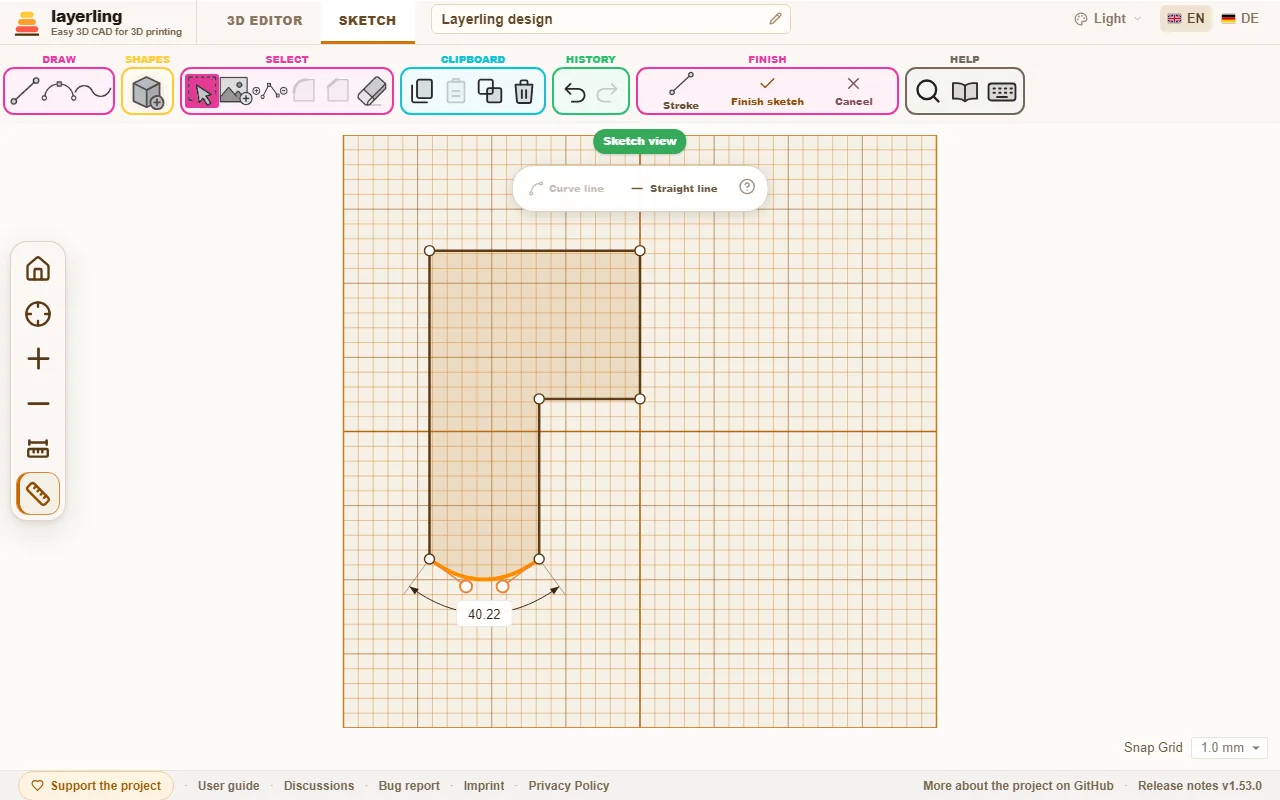
Reading and typing angles
Click a corner point where two straight lines meet: next to the lengths, layerling shows the angle between them in degrees, with a small arc. On a closed outline it is the angle inside the shape, so a dent reads above 180°. Click the value and type a new angle. One of the two lines then turns about the corner and keeps its length, and the other stays where it is. The line that turns is drawn dashed; Tab switches to the other one, Enter applies and Esc cancels. What hangs at the far end of the turned line goes with it.
Moving a point changes three angles: at the point itself and at the two neighbouring corners at the far ends of its lines. So layerling shows those two as well, and each can be clicked and typed. That way you set, say, the bottom left corner to 75.5° while the top left point, which moves for it, is selected. You can calculate here too, e.g. "90-14.5".
A corner shows no angle where a curve meets it, or where more than two lines meet. The “Show measurements” button on the side bar hides the angle together with the lengths.
Rounding or chamfering corners
Click a corner point and choose “Fillet corner” or “Chamfer corner”. A small field appears for the “Radius” or the “Distance”. Enter the size and confirm with the check mark. This works for corners between two straight lines.
Several corners at once work too: select them with Shift and a click each, or pull a frame round them, and choose “Fillet corner” or “Chamfer corner” from the bar that appears. All of them get the same radius or distance. Where two selected corners share a side, each takes at most 45 % of it, so a rectangle rounded all round comes out alike at every corner. Points that are not a corner between two straight lines are left out, and the message says how many. A frame round a whole shape, or a click inside it, selects its corners and its lines together, and the bar then offers “Curve line” and “Straight line” for all the selected lines next to the corner tools.
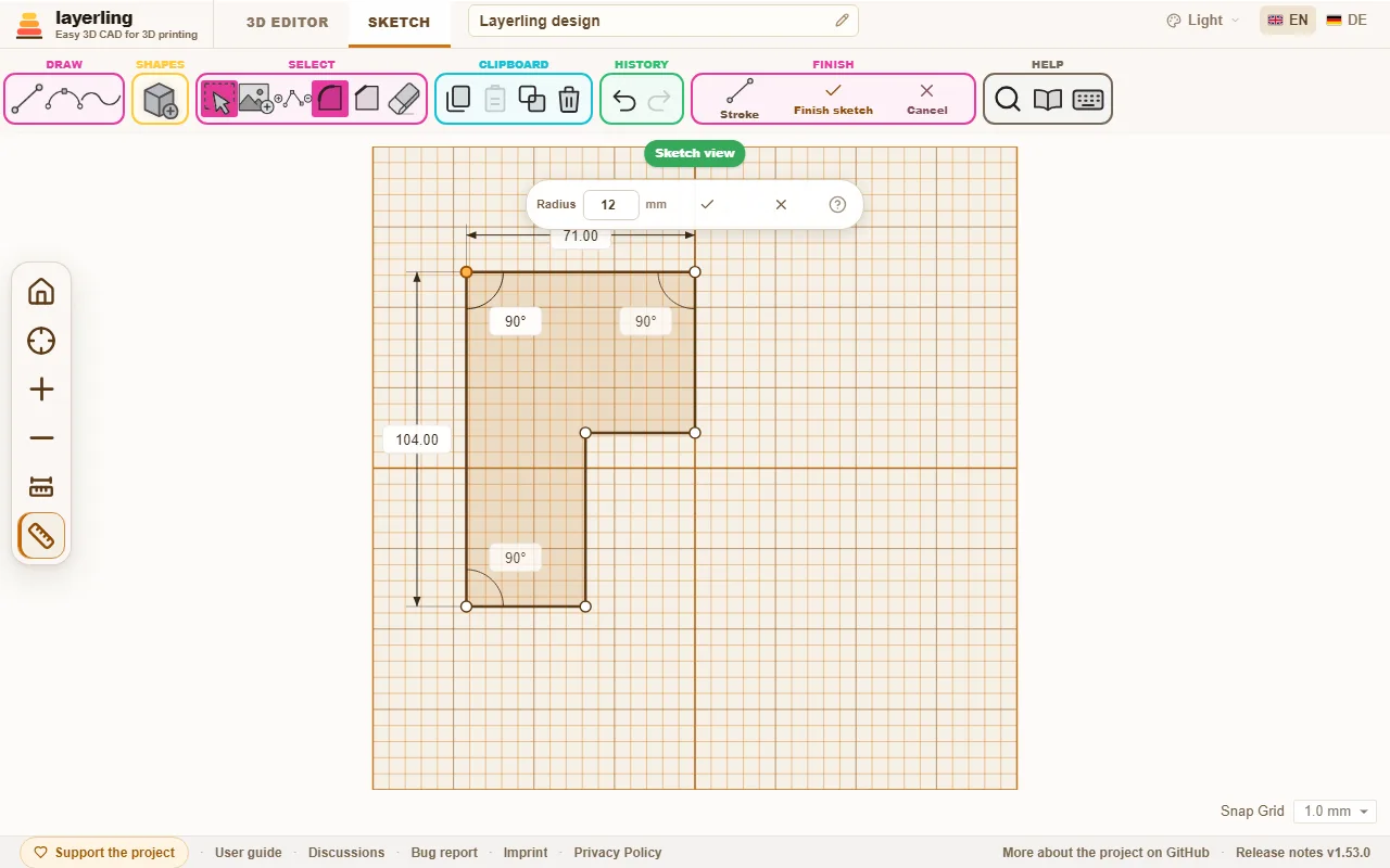
Construction lines
A construction line helps you place points without becoming part of the body. It is drawn dashed and never counts as outline: you can pull it as far beyond the shape as you like and the body does not grow.
- Switch on “Construction line” in the “Draw” group. New lines, those typed by measure too, are then construction lines. The button switches back to normal lines.
- A line you have drawn already becomes a construction line when you click it and choose “Construction”. “Make a line” makes it a normal line again.
- New points snap to where a construction line crosses another line, a blue ring shows it, and to the ends of the construction line. That is how you put a corner on a middle, at a fixed distance from an edge or on a crossing, without calculating.
- A construction line does not cut the outline apart where it crosses it. When revolving it may lie to the right of the axis too.
Making a body from it
Click “Finish sketch”. The outline stands as a body on the workplane. In its settings you change the height, the colour and everything else as with any other shape. When you resize it, layerling builds it again from the sketch a moment later, and the sketch grows with it. So it stays an exact body that takes chamfers and fillets, and the next time you edit it the sketch has the size the body has.
If the workplane lies on the side of a body, you draw the way you look at that side: up in the sketch is up on the finished body too. The faint outline of the body in the sketch view shows where it stands. If the workplane cuts through a body, the sketch view shows the outline of that cut instead, so a hollow body appears as a ring and you can line the sketch up with its walls. A point you set or drag close to a corner of these outlines snaps exactly onto it; a small blue ring shows it. That way you take edges of other bodies into the sketch, even when the workplane does not lie exactly on them.
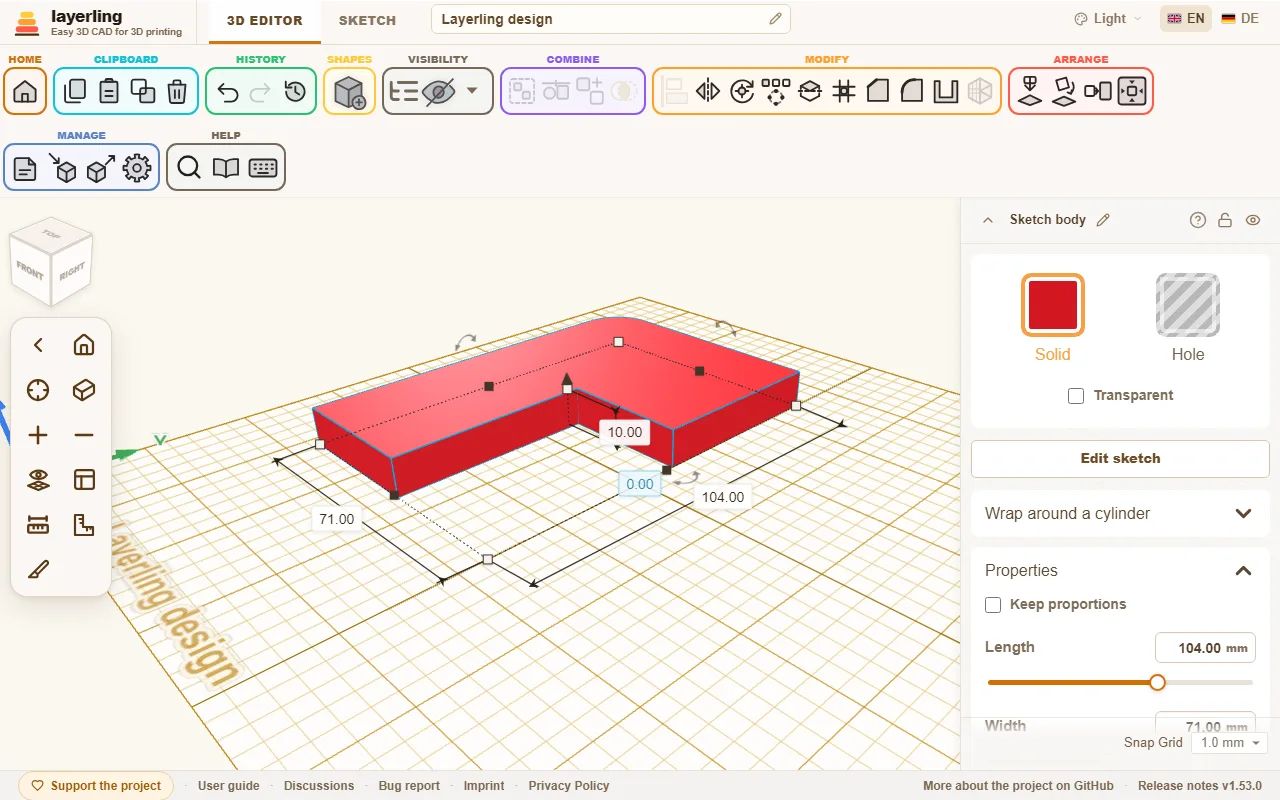
With “Edit sketch” you can return to the sketch at any time to change it. A double click on the body does the same, as in Tinkercad (a locked body stays closed); “Double-click opens the sketch” in the settings switches that off. Edge treatments you already made on the body are lost, though, because the edges are created anew.
Revolving
When revolving, you draw half the cross-section to the left of the axis shown in the sketch. Next to it you see a 3D preview of the revolve. It shows at once what the body will look like. The outline must be closed. At the end click “Finish revolve”.
A revolved body is an exact body, like an extruded one: it takes chamfers and fillets, and you can hollow it, for a cup or a vase. A body revolved with an older layerling is a mesh; open “Edit sketch” and finish it again to make it exact. A profile that reaches across the axis cannot be built exactly and becomes a mesh, as before.
Building as a stroke
Normally the area inside a closed outline becomes the body. With “Stroke” in the “Finish” section you build the line itself instead, with a width you set. Tick “Build as a stroke” in the panel; the sketch shows straight away what comes out.
- A closed outline becomes a frame. “Position” says where the wall lies: “Centred” on the drawn line, “Inside” within it or “Outside” outside it. Outside is handy for a tolerance: draw the outline of a hole, a dovetail for instance, and give it a 0.2 mm stroke outside to get the gap the print needs.
- An open line becomes a stripe, centred on the line. “Ends” sets how its ends look: “Flat”, “Square” (longer by half the width) or “Round”.
- “Corners” applies to both: “Sharp”, “Round” or “Bevel”.
The sketch keeps the drawn line. Open it again and you go on changing line and stroke; untick the box and the area is built again. Curves are broken into short straight pieces for it. A revolve has no stroke.
Fill and silhouette
You can set the stroke without opening the sketch too: in the properties of a sketch body, choose “Area”, “Stroke Outside”, “Stroke Inside” or “Stroke Centred” under “Fill”, with “Line Width” and “Corners”. The body is built again straight away, where it stands. These match the fill modes of Tinkercad's SVG import: default, outer line and inner line. “Wider” keeps the area filled and grows it by the line width all round, with sharp, round or bevelled corners: a base layer under a logo for a multicolour print, which the stroke outside alone would only give as a ring.
“Silhouette (No Holes)” leaves out every outline lying inside another: holes and whatever lies in them. Only the outer outline stays. Together with “Stroke Outside” it makes a cookie cutter: import an SVG twice, once with the silhouette as an area for the base and once with the silhouette and 1 to 2 mm of stroke outside as the wall. The switch is in the “Stroke” panel in sketch mode as well.
Fillets and chamfers on the edges go when the body is built again, as when the sketch is edited.
Slanted walls, for stamps
An extruded sketch has vertical walls. A stamp, an embossing die or a punch wants slanted ones, outside and inside, with the same wall thickness all the way. Layerling has no draft angle for an extrusion, but for plain outlines the “Taper” gets you there. One way that works:
- Draw the outline with the hole it needs and make a body of it. Duplicate the body (Ctrl+D).
- On the first body, switch on “Silhouette (No Holes)”, so the hole is filled, and give it a wider bottom than top with “Taper”.
- On the copy, open its sketch again and delete the outer outline, so that only the outline of the hole is left. Finish the sketch, switch the body to “Hole” and give it a narrower bottom than top with “Taper”.
- Move the hole into the first body, where the hole was, and group the two.
The walls now slope outside and inside. Taper scales the whole outline, so this is exact for plain shapes, where you can choose the sizes so the walls run parallel, and only an approximation for fine details such as lettering.
A picture as template
With “Add Image” you put a photo or a drawing under the sketch and trace it. You can set its size, opacity and position. Once the picture sits right, lock it with L so you do not move it by accident while drawing. A locked image is out of the way: clicks go through it, so you can pick lines and points on top of it and drag a frame over them. To select it again, for example to unlock it, Alt+click it. If its settings at the right edge cover the picture, drag them away by their title bar; a double-click on it docks them again.
Under “Align” you line up a photo that was not taken straight:
- “Rotation”: Turn the picture about its centre, with the round handle above its frame or as a number in degrees. With Shift the handle snaps in 15° steps.
- “To X = 0” and “To Y = 0”: put the picture's centre on X = 0 or Y = 0. For a revolve, X = 0 is the axis, so the picture then lies symmetric about it.
- “Calibrate”: Click two points in the picture whose distance you know, the ends of a ruler or a known diameter, and type the real distance. The picture is scaled evenly so that distance is right; the first point stays where it was.
- “Crop”: The handles on the frame now crop the picture instead of scaling it; what is cut away stays stored and comes back with “Show whole picture” or when a handle is pulled out again.
All four touch the reference only, never the sketch.
Keys in sketch mode
| Key | Effect |
|---|---|
| Esc | end the line chain, clear the selection |
| Delete | delete the selected element |
| Ctrl+C | copy the selection |
| Ctrl+X | cut the selection |
| Ctrl+V | paste |
| Ctrl+D | duplicate the selection |
| Ctrl+Z | undo |
| Shift | while drawing: snap the line in 15° steps; while dragging: keep movement on one axis |
| digit, <, Tab, Enter | while drawing: type and set the length and angle of the next line |
| R | rotate the closed sketch by 45° |
| L | lock or unlock the template image |
8. Text and curved lettering
Raised or engraved lettering in seven typefaces or one of your own, and if you like along a circular arc, such as on a coin, a lid or a ring.
Adding text
Choose “Text” in the shape library and place it. In the “Text” field on the right, type what it should say. The settings below:
- “Font”: Seven typefaces are available: Multilanguage, Sans, Serif, Script, Monospace, Rounded and Stencil (letters made of straight lines). New text starts in Sans. Accented letters such as ä, ö, ü, é and the € sign are in every typeface. Fonts of your own come on top, see Your own fonts below.
- “Letter size”: How big the letters are, seen from above; “Height” sets how thick they are.
- “Height”: How far the lettering stands out from the surface.
- “Bevel”: Rounds the letter edges so they look softer. With “Segments” you decide in how many steps.
- Size: You set the length and width of the line as with any shape. Drag the handles or type the dimensions.
Text is at first a single body. If you want to treat the letters individually, click “Separate Parts”. Then every letter is a shape of its own.
The edges of text can be chamfered or filleted too, straight or curved, see Breaking edges and hollowing bodies. Use small sizes such as 0.2 to 0.5 mm, because the strokes of the letters are narrow.
Your own fonts
Besides the seven built-in fonts you can use any font of your own: a font file from your computer or, in Chrome and Edge, a font installed on your computer. Choose “Your own fonts …” at the bottom of “Font”. The “Your own fonts” window opens.
- “Choose a font file …” takes a TrueType file (
.ttf), an OpenType file (.otf) or a WOFF file (.woff). You can also simply drag the file into the window. - On Windows the installed fonts live in the Fonts folder (
C:\Windows\Fonts). The browser's file dialog hides it. Open it in Explorer instead and drag the font into the “Your own fonts” window. Fonts installed for you alone live in%LOCALAPPDATA%\Microsoft\Windows\Fonts, which the file dialog shows too. On a Mac fonts live in/Library/Fontsand~/Library/Fonts. - “Font from the computer …” lists the fonts installed on your computer. The first time, the browser asks whether layerling may read them. The search field finds a font quickly, a click takes it.
If a text is selected, it gets the new font at once. Otherwise the font shows up under “Font” in the “Your own fonts” group, and “Use” in the window puts it on the selected texts. Fonts of your own work like the built-in ones: text on a circular arc, chamfers and fillets on the edges and the STEP export all work the same. Letters a font lacks are taken from Sans.
Arabic and Hebrew
Arabic, Persian, Urdu and Hebrew are written right to left: the first letter stands on the right, and in a mixed text such as "Name عربي" only the Arabic word runs backwards, digits stay as usual. Arabic letters join their neighbours the way the script asks, and lam-alef becomes a ligature. This needs a font that has these letters; the built-in ones do not. Add one of your own, such as Arial, Tahoma or Segoe UI on Windows, or a free one such as Noto Naskh Arabic, Noto Sans Arabic or Amiri. Vowel marks sit on the letter they belong to. Text on a circular arc, outline, silhouette, layers and name tags work with it as with any other text.
What works in which browser
| Browser | Choose a font file | Font from the computer |
|---|---|---|
| Chrome and Edge on a computer, the installed layerling app too | yes | yes, after the browser asks |
| Firefox | yes | no |
| Safari on a Mac | yes | no |
| Tablet and phone | yes, from the device's files | no |
Web pages may not simply read the installed fonts. Only Chrome and Edge have a permission for it, and only on secure pages, over https as on layerling.com. When layerling runs over http, say on your own server or as a Docker install in your home network, “Font from the computer …” is missing; drag the font over from Explorer then. In the other browsers you choose the font file from the fonts folder, with the same result. If you declined the question in Chrome or Edge, allow it again in the site settings, behind the padlock to the left of the address.
layerling cannot read WOFF2 files (there is almost always a TTF or OTF version), font collections (.ttc, several fonts in one file) or colour emoji fonts. From very large fonts, such as Chinese ones, layerling takes the first 8000 characters. A variable font is read in its default setting, usually the regular weight.
Some fonts, script and variable fonts above all, draw a letter from strokes that overlap. layerling merges them into one clean outline when it reads the font, so the body stays printable. Such letters are then made of very short straight pieces instead of curves; it does not show.
Where the fonts are kept
A font of your own stays in this browser on this computer. Another browser or another computer does not know it until you add it there too. Clearing the browser's site data clears the fonts as well. In the “Your own fonts” window the bin removes a font from the browser. Your designs lose nothing by it, as the next section shows.
Passing on designs with a font of your own
A design does not store the font file, only the outlines of the letters its texts use, those in earlier steps of the history included. If a text says "Hello", only H, e, l and o travel with it. That holds for every way a design is saved: in the browser, on your own server, as a .lyl file and in “Custom shapes”.
So:
- The design opens correctly anywhere, also on a computer without the font. The texts look the same and can be moved, turned, scaled and filleted.
- New letters need the font. If someone without the font types a letter the design did not bring along, layerling draws it from Sans. Under “Font” the font is then marked “only the design's letters”. Adding the font file brings back every letter.
- Exports hold geometry only. STL, 3MF, OBJ, STEP and SVG contain bodies and outlines, no font.
- Older layerling versions do not know fonts of one's own yet and draw such texts in Multilanguage.
Licences: Fonts are protected by copyright, and their licence says what you may do with them. The embedded letter outlines are what PDF files take along from a font, and most licences allow that. Some commercial fonts, though, forbid passing on even single letters. Before you pass on or publish a design with a font of your own, check the font's licence. Free fonts such as those from Google Fonts (mostly under the SIL Open Font License) can be passed on without worry. For a printed part or an exported STL it does not matter: they hold no font any more, only geometry.
Raised or engraved
- Raised: Place the text on the surface and group it with the body. It grows out as a relief.
- Engraved: Switch the text to “Hole”, let it reach a little into the surface and group it with the body. The letters are then engraved.
For lettering on a side face, first put the workplane on that face, see View and workplane.
Outline, silhouette and wider
A text need not be built as filled letters. “Fill” in the properties offers the same choice as Tinkercad:
- “Filled”: the letters as they are.
- “Outline”: a line along the outline of the letters, half inside and half outside it.
- “Outer line”: a line round the outside of the letters.
- “Inner line”: a line on the inside of the letters.
With a line chosen, two settings appear right under the list: “Line Width” sets how thick the line is, “Corners” how it goes round the corners (“Round”, “Bevel” or “Sharp”). The rarer settings are under “More”: “Silhouette (No Holes)” leaves out the holes in O, A or e, and “Wider (base for a multicolour print)” keeps the letters filled and makes them thicker by the line width all round; letters that touch grow into one piece.
With a line outside, a centred line or "Wider" the box of the text grows, while the letters keep their size. “Bevel” and “Segments” exist for filled letters only.
Layers and name tags
A name tag for a multicolour print is a text in layers: the letters on top, under them the same text a little wider in a second colour, at the bottom a plate without holes in a third. layerling makes it in one click:
- A new name tag: choose “Name tag” in the shape library and place it. It says "Name" in white letters on a red rim and a dark plate.
- From a text: select the text and click “Make layers” at the top of its settings.
All settings of the tag are in the card “Name tag”, at the top of the settings:
- “Text” and “Font”, fonts of your own too. The tag grows with the words.
- “Letter size”: how tall the capital letters are, in mm. All layers follow and stay lined up.
- “Layers”: one row per layer, from the top down. Each row has the colour (click the coloured square), how much wider the layer is than the letters, its height and “No holes”, which fills the holes in letters such as O and A. “Corners” sets how a wider layer goes round the corners of the letters: “Round”, “Bevel” or “Sharp”. The top row is the letters themselves. + adds a layer at the bottom, – takes the bottom layer away. A tag has two to six layers.
- “Key ring hole”: gives the bottom layer a straight tab with a round end and a hole for a key ring; the tab grows with the hole. A 3 mm hole, the default, makes a tab 6.5 mm wide that sticks out 6.75 mm, the hole's edge 2 mm from the edge of the bottom layer. Choose the “Hole diameter” and the “Side”: “Left”, “Right” or “Top”. The hole goes through every layer it touches, and the tab moves along when you change the words, the letter size or the font.
- “Letter edge”: rounds or chamfers the top edge of the letters on the top layer, the way a printed tag is finished: “None”, “Round” or “Chamfer”, with the “Edge size” (0.4 mm to start with, at most as high as the layer). It works for every font and word. The edge is part of the letters' mesh, so the edge tool takes such a text as a mesh, which for a text this fine is heavy; pick the edge here instead.
Every change shows at once. The tag is a bundle: it moves as one, and each layer stays a body of its own in its own colour, the way a slicer needs them for a multicolour print. To round or bevel the edges of one layer, click “Edit bundle” and pick the layer, see Breaking edges and hollowing bodies.
Many name tags at once
Type the names into “Name list”, one per line, up to a hundred. The button below says how many tags it will make, for example "Make 12 name tags". Every tag gets the same layers, letter size and key ring hole and is an object of its own; they are laid out in rows below the first, 5 mm apart. A plain text has the name list too, further down in its settings.
Icon tags
An icon tag is the same tag with an SVG icon instead of letters: a heart, a cloud, a club's logo. The icon on top, under it the same outline a little wider in a second colour, at the bottom a plate without holes.
- A new icon tag: choose “Icon tag” in the shape library. A small window opens: click “Browse…”, pick an SVG file, check the picture, type the “Width (mm)” of the icon and click “OK”. The tag stands in the middle of the plate, in the same layers as a new name tag.
- From a sketch body: an imported SVG, or a sketch you drew, has “Make layers” at the top of its settings.
The card “Icon tag” at the top of the settings holds:
- “Another SVG…”: puts another SVG's icon on the tag; the layers and the width stay as they are.
- “Width”: how wide the icon on top is, in mm. All layers follow and stay lined up.
- “Layers”: the rows as on a name tag - colour, how much wider, “Corners”, height and “No holes”, + and –, two to six layers. The top row is the icon itself.
- “Count”: how many tags you want, 1 to 100. “As many as fit” works it out from the plate of the printer chosen in the settings, for small logos a full plate. The button below makes them, 5 mm apart, laid out on the middle of the plate; the first is the tag itself.
The SVG needs closed outlines; a drawing of open lines only cannot become a tag. A sketch body whose fill is a line keeps it: the area of that line is the icon.
Text on a circular arc
Should the lettering not run straight but follow the edge of a coin, a lid or a ring? For that there is the setting “On arc”.
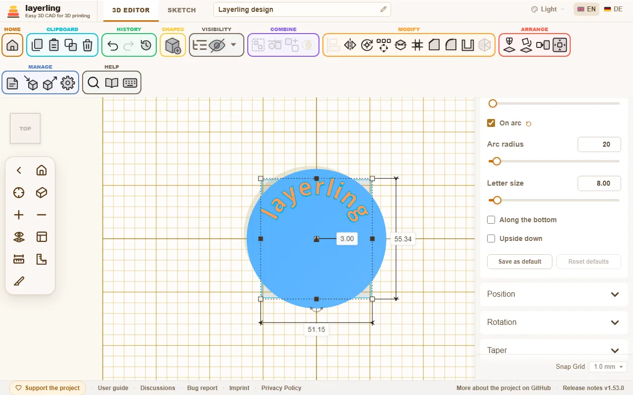
Once you switch it on, the text runs along the circle. All letters stand on the same baseline, as evenly as with normal text. There are four settings:
- “Arc radius” (5 to 500 mm): The radius of the circle the letters' baseline runs on.
- “Letter size”: How tall the letters are. It no longer depends on the width of the shape.
- “Along the bottom”: Moves the text from the top of the circle to its bottom. The letters then point with their heads to the centre.
- “Upside down”: Turns only the letters over so you can read them from the other side. The text stays in its place on the circle.
The centre of the circle is the centre of the shape. That is why aligning works as usual: if you centre the text with a cylinder or ring, it sits exactly concentric on it. When you pull a handle, radius and letter size grow together, so the lettering is not distorted.
9. Threads, gears and other parts
Screws, nuts and tapped holes that fit together, plus gear, spring, bent tube, dovetail, teardrop hole, counterbore and countersink.
Besides the basic shapes, the library contains some parts that would be tedious to put together yourself. All of them can be changed afterwards in their settings.
Threads
Choose “Thread” in the shape library. Under “Type” you decide what it should be:
- “Threaded rod”: a cylinder with thread, for example a screw without a head.
- “Screw”: with a head. You choose the “Head”: “Socket head”, “Countersunk” or “Hex head”.
- “Nut”: the matching nut.
- “Tapped hole”: a tapped hole. It is a hole. Drag it into a part, group both, and the part has an internal thread.

You pick the size under “Size” from a list: metric from M2 to M12, the inch sizes UNC and UNF from No. 4 to 1 inch, and the pipe threads G1/16 to G4. If you choose “Custom”, you set “Diameter” and “Pitch” yourself. For an inch size or a G size the field asks for “Threads per inch” instead of the pitch in millimetres.
The list groups the sizes by series, and a line under the field names the series of the size you picked, with examples you know from everyday life:
- M, metric coarse: the ISO metric coarse thread to ISO 261, as on standard screws and nuts.
- UNC, US inch coarse: the camera and tripod screw is 1/4"-20 UNC (ISO 1222), larger tripod heads use 3/8"-16 UNC.
- UNF, US inch fine: the same diameters as UNC with a finer pitch (ASME B1.1).
- G, pipe thread: a shower hose connects with G1/2, a washing-machine inlet hose with G3/4. A garden tap ends in G3/4, smaller taps in G1/2; that is where the tap connector of a click-on hose system screws on.
The G sizes are the parallel Whitworth pipe threads to ISO 228-1, found on fittings for water, gas, hydraulics and pneumatics. The size names the pipe, not the thread: a G1 measures 33.249 mm across the thread. Choosing a G size sets the profile to “Whitworth (55°)”, and choosing a metric or inch size sets it back to “V-thread (ISO)”. A “Trapezoidal” or “Round” profile you picked yourself stays. The standard only defines the thread, so the head of a screw and a nut on a G size get the same proportions as on a diameter you set yourself. The tapered pipe threads R, Rc and Rp are not included.
More settings:
- “Direction”: “Right-hand” or “Left-hand”.
- “Profile”: “V-thread (ISO)” is the standard profile of metric and inch threads, “Whitworth (55°)” that of the G pipe threads: 55° with rounded crests and roots. “Trapezoidal” and “Round” have flat crests and roots. That usually prints more reliably because no thin tips result.
- “Custom (trapezoid)”: A trapezoid you shape yourself, with a flat crest and a flat root of the same width. “Flank angle” is the angle between the two flanks of a tooth: 60° is the sharp V thread, 30° the trapezoid thread, and at 90° or less no flank is flatter than 45°, so the thread prints without supports. “Thread depth” and “Core diameter” are one measure said two ways: the core diameter is the diameter minus twice the depth, and changing one changes the other. A new own profile starts with the V thread's depth at 60°. The depth has limits that depend on the angle and the pitch: not shallower than a tenth of the pitch, not deeper than 40 % of the diameter, and not so deep that the two flanks take more than nine tenths of the pitch. If you change the pitch, the depth follows in proportion; if you scale the thread, so does the depth. The play and the chamfers work as with the other profiles. Through the MCP bridge the profile is
customwiththreadFlankAngleandthreadDepth. - “Clearance (XY)”: For nut and tapped hole, the room that makes sure a printed pair really turns. The coarser your printer works, the more clearance the pair needs. It is the extra room across the whole diameter, and the gap between the flanks of a V thread is only about half of it, so a printed pair needs more than you might expect: new nuts start at 0.4 mm, 0.3 is tight and 0.5 loose. Print a test pair first. Rods and screws have a clearance of their own here, which makes the bolt that much thinner in diameter. It is set to 0. Which side gets the room depends on what you pair:
- Printed screw and printed nut: leave the screw at 0 and give the nut the room (the 0.4 mm it starts with).
- Real screw in a printed nut or tapped hole: the printed side takes all of it, so the nut keeps its 0.4 mm. A tighter 0.3 mm is worth a test if the screw wobbles.
- Printed screw in a real nut: the real nut has no play, so the screw has to be thinner: 0.3 to 0.4 mm here, as much as a printed nut would have.
- “Play along the axis (Z)”: For nut and tapped hole, the play along the axis, on top of the “Clearance (XY)”. Every tooth of the nut gets this much thinner, the diameter stays as it is. The reason: the “Clearance (XY)” works on the diameter only and opens the flanks of a V thread to about 0.58 of its value. Anyone who wants air between the flanks has to open the diameter wide and gets sideways slop for it. The play along the axis sets the two apart. It is set to 0, so a saved thread does not change, and it goes up to a fifth of the pitch at most, because above that nothing would be left of the nut's teeth. The field exists for nut and tapped hole only; rod and screw keep their own clearance. More below under "Threads for 3D printing".
- “Chamfer, top end”, “Chamfer, bottom end”, “Head chamfer” and “Rim chamfer”: Chamfers at the ends so the thread starts cleanly and the head has no sharp edge. Each end of a rod, nut or tapped hole has its own chamfer, so the top can be long and the bottom short or none. A screw has only one at its tip, labelled “Chamfer”. On a nut or tapped hole the chamfer is the room the mouth opens beyond the outer diameter; the cone runs at 45 degrees on down to the thread core, so no ledge is left at the outer diameter.
Switching a thread between “Threaded rod” and “Tapped hole” keeps its length. A nut and a screw start from their standard measures.
- “Quality”: How finely the thread is calculated. Higher is more exact, but slower.
Printed threads are a topic of their own. Make the screw-and-nut pair as a test first before you print a large part, and adjust the clearance to your printer.
Threads for 3D printing
A printed thread needs air in two places, and they act differently:
- Clearance in the diameter (“Clearance (XY)”): makes the nut wider. The screw then has half the value as air on each side, 0.2 mm at 0.4 mm. The thread turns easily, but the screw can wobble sideways.
- Play along the axis (“Play along the axis (Z)”): makes the teeth of the nut thinner. The screw can then move back and forth along the axis by that value when it is not tightened. There is no extra air to the side for it.
Together they make the gap between the flanks: about 0.58 times the clearance in the diameter plus the play along the axis. An example for a 0.3 mm gap: it used to take 0.5 mm in the diameter, that is 0.25 mm of air on each side. Now 0.2 mm in the diameter (0.1 mm on each side) and 0.2 mm along the axis do it, and the gap is 0.32 mm.
Consequences to know
- The screw has play along the axis. Without load it can move back and forth by that value. For fastenings, lids and housings that does not matter; for a lead screw that has to position exactly it does, so keep it small or at 0 there.
- The nut's teeth get thinner. With 0.3 mm at a pitch of 1.75 mm every tooth is almost a third thinner at its middle and so clearly less strong. For heavily loaded parts take a coarser thread instead.
- More to calculate. The tooth shape gets extra points, so the thread has more triangles and takes a little longer to compute.
- No true arc in the STEP export for the Whitworth profile. A “Whitworth (55°)” thread with play along the axis goes to the edge tool and the STEP export as a tooth shape made of straight pieces, not with the true circular arcs. At 0 everything stays as before.
Tips
- A test pair first. A screw and a nut, each only 4 to 6 mm tall, take a few minutes. Print three pairs with different play side by side and take the one that turns easily and does not wobble.
- Start with values that often fit. Clearance in the diameter 0.2 to 0.3 mm and play along the axis 0.2 mm. If the screw wobbles sideways, lower the clearance in the diameter; if it jams, raise the play along the axis. If you would rather do without the play along the axis, use 0.4 mm in the diameter as before.
- The play along the axis should be at least one layer height. What lies below one layer the printer does not resolve. With a layer height of 0.2 mm, 0.2 mm is a good start; with 0.1 mm, less is enough.
- Print screw and nut upright. The axis points up, so every turn lies in whole layers and the flanks come out clean. Lying down, the flanks sag.
- Fine pitches are hard. Below about 1 mm of pitch the turns often fuse. A coarser thread, or a “Trapezoidal” profile with flat crests, prints more reliably than a fine V thread.
- Avoid thin tips. The V thread has a narrow tip that the printer hardly hits with its nozzle width. The “Trapezoidal” and “Round” profiles have flatter teeth.
- Deburr and run it in. The first turns are often stiff because small remains of the print stand on the flanks. Turn it back and forth a few times and it runs easier. The chamfer at the start helps threading it in.
- Another printer or filament. The play depends on the printer, the material and the nozzle. Print the test pair again when you change either.
The edge tool takes a thread as its exact body. You can chamfer or round the part that carries it with the thread already in place, or the rims of a screw head, see Breaking edges and hollowing bodies. Working out a thread's edges takes a while: a few seconds for an M6, about half a minute for a G1/2 pipe thread. The quickest way to break the edge of a screw head is still the head chamfer in the properties.
Gears
“Gear” comes as “Spur gear”, “Helical gear”, “Herringbone gear” and “Bevel gear”, and as “Ring gear” and “Rack” (further down). New gears have “Involute” under “Tooth Shape”: teeth with involute flanks, as gear generators and engineering use them. Such teeth roll cleanly on each other. You set the number of “Teeth” and the “Module (mm)”, and the size follows: the outside diameter is module × (teeth + 2), the pitch circle module × teeth. New gears start at module 2. Two gears mesh when they have the same module and the same “Pressure Angle” (usually 20°) and their centres stand (teeth + teeth) × module / 2 apart. Select both gears and the properties panel gives that centre distance and how far apart the centres are now. If a tooth then meets a tooth instead of a gap, turn one of the gears by half a tooth, which is 180° divided by its number of teeth. “Backlash” takes a little off the teeth so a printed pair does not bind. The value is for the pair, and each gear takes half of it; 0.2 mm is a good start, 0 gives the exact gear. Below the base circle the flank runs straight down to the root and is not undercut as a cutter would do it. That suits printing, but a very small pinion below about 17 teeth may rub slightly at the root.
A helical gear adds the “Helix Angle”. With involute teeth it is the true helix angle on the pitch circle: two helical gears mesh when they have the same module and the same angle, one positive and the other negative. The “Herringbone gear” is two helical halves turning opposite ways: the teeth run one way up to half the height and back after it, like an arrow. That has two advantages for 3D printing: the gear centres itself on its shaft, and it has no axial thrust, because the forces of the two halves cancel. A helical gear, in contrast, pushes sideways along its axis. You set the “Helix Angle” and the “Helix quality” as for the helical gear; the angle applies to each half. Two herringbone gears mesh when they have the same module and the same angle with opposite signs, one positive and the other negative. There is no groove in the middle, as on milled herringbone gears: the two halves run into each other without a step. The edge tool and the STEP export take the herringbone gear as a triangle mesh, not as an exact body.
The bevel gear takes the involute teeth and makes them smaller towards its top. That is an approximation, not an exactly worked out bevel pair.
“Round” are round teeth made of arcs, like Tinkercad's Useful gear: tip and gap run into each other without a corner. Small gears print more forgivingly that way and turn more easily, and on a knob the teeth make a pleasant grip. Round teeth are set by “Teeth”, “Module (mm)” and “Backlash” too; they have no pressure angle. They stand lower than involute teeth, so the outside diameter is module × (teeth + 1.2). Round gears with the same module mesh, at the same centre distance as involute ones; with an involute gear they do not fit.
“Simple” are the straight teeth every gear had so far. There you set “Tooth Size” and “Tooth Width” by hand. Older designs keep them until you change the tooth shape. All three tooth shapes have the “Center Hole”.
The “Ring gear” has its teeth pointing in: a ring that a smaller gear runs inside, like the outer wheel of a planetary set. You set it like an involute or round gear by “Teeth”, “Module (mm)” and “Backlash”, plus the “Rim”, the ring outside the teeth. Its outside diameter is module × (teeth + 2.5) plus twice the rim, with round teeth module × (teeth + 1.7). A gear of the same module runs in it when its centre stands (ring teeth − its teeth) × module / 2 from the ring's centre; select both and the properties panel gives that distance. For a planetary set, ring teeth = sun teeth + 2 × planet teeth, for example 30 = 12 + 2 × 9. A ring gear has no centre hole, it is the ring itself. Between 26 and 33 teeth its tips are up to a quarter module shorter, because a tiny edge would otherwise form at the base circle; meshing is not affected.
The “Rack” is the gear of endless radius: a bar with teeth along one side, whose flanks are straight lines at the pressure angle with involute teeth. Its width (along X) is teeth × pitch, the pitch being π × module, so racks of one module line up end to end, each end falling in a gap. Its length (along Y) is the thickness of the bar and free, as long as the teeth and half a millimetre of bar fit in. The teeth point to the front, towards the viewer of the home view; turn the rack as you need it. A gear of the same module rolls on it when its centre stands its teeth × module / 2 in front of the pitch line; the pitch line lies a module behind the tooth tips, 0.6 module with round teeth. Ring gear and rack come with involute and with round teeth, not with simple ones; switching the gear type keeps the module.
The edge tool and the STEP export take every gear as its exact body, involute flanks as smooth curves. A helical gear on an oval footprint stays a triangle mesh, and so does a helical gear with involute teeth from about 31 teeth. Small teeth limit how far edges can be rounded: on a gear with simple teeth, 30 mm across with 12 teeth the flat between two teeth at the foot is only about 0.65 mm wide, so rounding every edge works up to about 0.5 mm, and on a bevel gear, whose top is smaller, up to about 0.4 mm. A helical gear's teeth lean, which narrows that flat across its slanted edges: the larger the helix angle against the gear's height, the smaller the rounding that fits. The edges of its two flat ends can be rounded, but chamfering just those edges fails in the CAD kernel; round them, or chamfer all edges together at a smaller size, such as 0.2 mm.
Springs
The “Spring” has “Turns” and a “Wire”. Together with the height they decide how soft the spring is. “Winding” sets which way the wire runs: “Right-hand” like a usual compression spring, or “Left-hand”.
The edge tool and the STEP export take a spring as its exact body: a round wire along a helix, cut square at both ends. You can round or chamfer those two wire ends, for instance.
Bent tubes
A “Bent Tube” consists of up to twelve sections: a straight piece followed by a bend. For each you set the “Straight length”, the “Bend angle”, the “Bend radius” and the “Roll angle”. The section you are editing is lit up in orange on the tube, so you can follow the order. A roll angle of 0° bends within the plane of the workplane, at 90° the tube bends upward. The profile can be round, square, hexagonal or octagonal, the inside likewise, or fully solid. If the tube runs into itself, layerling warns you.
Loft
The “Loft” joins one outline at the bottom to another at the top, like a loft in Fusion: a hose adapter from one diameter to another, a square fan onto a round duct, a stand that turns round towards the top. For each end you pick “Bottom Outline” and “Top Outline”: “Circle / ellipse”, “Rectangle” with “Bottom Corner Radius”, or “Polygon” with its number of corners, plus the width and length of each end and the height. “Top Offset in Width” and “Top Offset in Length” move the top end sideways for a slanted transition; the bottom end stays where it is.
“Wall Thickness (0 = solid)” turns the solid body into a tube open at the top and the bottom. The opening is smaller by the wall at both ends, measured across; where the wall slants it is a little thinner. Drag the frame bigger and both ends grow along, while the corner radius and the wall keep their size.
“Smooth transition (%)” makes the transition smooth. At 0 the sides run straight from the bottom to the top, as on a cone. At 100 they leave both ends straight up and change their size in between along an S-curve: a hose adapter that flares smoothly from a narrow to a wide pipe, instead of running like a funnel. In between the slider mixes the two. A smooth transition works together with “Wall Thickness (0 = solid)”, a twist, a tilt and a sideways offset; a tube with a wall stays open at both ends. It is an exact body like the straight one, so its edges can be chamfered and filleted, but it is built through several sections and takes a little longer to calculate.
“Twist” turns the section evenly about the vertical on the way up, up to 360° either way; the sides then wind round. “Top Tilt, Front/Back” and “Top Tilt, Left/Right” tilt the top end, up to 45°: a positive value raises its front edge or its right side. The sections in between tilt by their share, so the wall runs smoothly into the slant. The highest point stays at the set height. If the height later becomes so small that the slanted end would reach under the plate, the tilt gives way until it fits. A bend along a path, such as a pipe elbow, is not something the loft does.
The loft is an exact body, twisted and tilted too: its edges can be chamfered and filleted, and STEP export keeps it. Add a flange with screw holes as usual and group them.
Hinge
The “Hinge” prints in one piece and moves afterwards (print-in-place): two leaves lying open flat on the plate, with alternating knuckles on one axis between them. The pin belongs to the back leaf and runs with play through the knuckles of the front one. You set the “Length (axis)”, the “Width opened” and the “Knuckle diameter”, plus the number of “Knuckles” (odd, so the pin is held at both ends), the “Pin diameter” and the “Leaf thickness”.
“Clearance” is the gap between the moving parts: around the pin, between the knuckles and in front of the leaves. With 0.4 mm a well-tuned printer usually breaks free with a small twist; if the parts fuse, raise it, if it wobbles too much, lower it. Print the hinge lying down as it appears on the plate, without supports. You can add holes to the leaves or group them into a larger part, such as a lid.
Knurling
The “Knurl” is a round grip with grooves all around, for knobs, thumb wheels and tool handles. Under “Pattern” you pick “Straight”, grooves along the axis as on a control knob, “Crossed”: two slanted rows of grooves cross into small diamonds, or “Round”: grooves and ridges along the axis as a soft wave of arcs, a pleasant grip without sharp ridges. Round grooves stay shallower than half a pitch, or the ridges would bulge at their foot; a depth too great gives way. You set the “Diameter” and the “Height”, the number of “Grooves” and the “Groove depth”; for crossed knurling also the “Groove angle” to the axis. The “Chamfer at the ends” breaks both ends at 45 degrees, as on a turned knob; 0 leaves them sharp.
Straight and round knurling are exact bodies, so their edges can be broken and rounded. Crossed knurling stays a mesh, because as an exact body it would take almost a minute to compute with 30 grooves. For a knob on a shaft, group the knurl with a hole, such as a “Thread” set as a tapped hole. Grooves shallower than 0.4 mm hardly any printer prints cleanly, and layerling does not set them closer than 0.8 mm around the grip: a thin grip gets fewer of them.
Dovetail
The “Dovetail” is the joint in which two parts lock into each other and can only be slid together sideways. You set the width at the wide end, the “Neck width” and the length of the tail. Copy the tail for the other side and make the copy a hole: “Clearance as a hole” then gives a little play so the joint does not jam after printing.
Teardrop hole
A hole lying on its side gets a bridge across its top when printed, and the bridge sags. The “Teardrop hole” therefore has a point on top: every layer rests on the one below, and the hole comes out round enough without supports. Set the “Diameter (round part)” to the size of the hole, about 3.4 mm for an M3 screw, and the “Hole length” long enough to reach through the part. The “Tip angle” is 90°, so the flanks meet at 45°. Most printers handle that cleanly; a flatter point needs more height, a steeper one saves it.
Make the teardrop a hole and group it with the part. Its length runs along the depth and the point faces up. For a hole in the other direction, turn it by 90° around the vertical axis.
Counterbore and countersink
A screw head often should not stand proud. The “Counterbore” cuts a round pocket for a socket-head screw (DIN 912), the “Countersink” a cone for a countersunk screw (DIN 7991). Both stand with the head end up: the “Head diameter” is the diameter of the pocket or the cone, the “Shaft diameter” the bore below it, the “Total length” the whole length. On the counterbore you set the “Head depth”, on the countersink the “Cone angle” (90° suits countersunk screws). The defaults fit an M3 screw.
Make the shape a hole and group it with the part. Let its top end a little above the surface the head should sit on, so the pocket opens cleanly. For the pocket of a hex nut, use a “Polygon” with six sides as a hole.
10. Measuring and notes
Tape measure, ruler and framing square, distances to the origin, notes that stay attached to a part, and reference points that things snap to.
To build a part exactly, you need to measure. layerling has several tools for that. None of them ends up in an export. Wall thickness and gaps inside a part are best measured in the section view with “Measure”.
The tape measure
The tape measure sits at the lower end of the camera bar on the left edge (“Tape measure”). It measures distances between corners, edges and faces. A click on it opens five buttons. If they cover what you want to measure, drag them by the grip on the left anywhere on the workplane; a double-click on the grip puts them back:
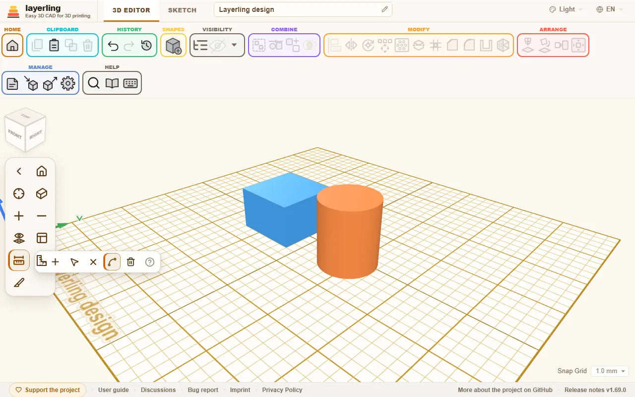
- “Add measurement”: Click one point, drag to the next and click it. The distance is labelled.
- “Move measurement points”: Grab the points and move them, the number follows.
- “Delete measurement part”: Afterwards click a measurement to remove it.
- “Measure whole edges”: A click on an edge measures all of it, the length of a circle for example. With this switched off, a click puts a point on the edge instead, and the second point goes anywhere, so you can measure the diameter or any other distance. Alt turns the switch round for one click. On a circle, the point across from the first one snaps in when the pointer comes near, and the points sit on the true circle, so the diameter comes out exact.
- “Delete all measurements”: Removes every measurement at once. Because this cannot be undone, layerling asks first; with no measurements there is nothing to do.
- “Mark the middle as a reference point”: Under the number of every measurement sits a small crosshair button. It puts a reference point in the middle of the measurement: after a click on a round edge, such as the rim of a hole, in the centre of that circle - on an imported mesh too, where nothing else marks the middle of a hole - and for a diameter or any straight measurement halfway along it. A shape you drag then snaps to the point with its centre. A point that is there already is not made twice.
Esc leaves measuring mode.
The ruler
You fetch the “Ruler” from the shape library. It is purely a measuring tool: it appears in no export and can neither be grouped nor cut. For every body that touches or overlaps the ruler, it shows the extent as a floating number right in the view. You can change that number right there, and the body follows. The floating plus symbol creates a copy of the measured shape.
The framing square
Sometimes you measure better at a right angle. Click “Place framing square” in the camera bar and then the workplane. A framing square with two arms at a right angle, with tick marks like a try square, is placed there. It has no body of its own either. Click close to the corner of a body, and its corner snaps exactly there.
The framing square lies on the workplane. If that sits on the side of a body, the square lies on that side too, see View and workplane. That is how you dimension on a vertical wall: put the workplane on the wall, place the square at its top left corner and click the handle until the arms point right and down.
- Dragging the handle moves it.
- A short click on the handle turns it by 90°.
- The × beside it removes it.
- The small button left of the handle switches what is measured from: the outside of a body (endpoint, an icon with lines) or its middle (midpoint, a crosshair).
If bodies stand at one of the arms, the framing square shows their dimensions automatically. That works on the base plate only, not on the side of a body.
When you select a body, the framing square shows in green how far it is from the corner, along both arms and in height. Click a green number to type a distance, and the body moves exactly there. With several bodies selected, they count as one: the ruler measures their shared outline, and a typed value moves them all together without changing their positions relative to each other.
With the midpoint, the green numbers count to the middle of the body, in height as well. That way you place a sphere with its centre exactly 15 mm from an edge, without subtracting the radius. On a wall you place a hole 40 mm from the left and 190 mm from the top like this: select the hole, switch to midpoint, type 40 and 190. The height there counts outward from the wall.
Both the tape measure and the framing square stay where they are while you sketch and come back to the 3D view. They are not saved with the design and not in the history, and they go when you reload the page.
Distances to the origin and while moving
In the settings under “Appearance” there are two switches for live dimensions:
- “Show movement dimensions” shows by how much you move while dragging.
- “Show origin distances” shows the distances of the selection to the origin of the plate, also with several selected bodies.
With “Dimensions always visible” the dimensions stay visible permanently.
Notes
A note records what the geometry does not say: "This screw is 0.3 mm too tight", "print the lid yet", "dimension from Peter". Place one with “Note” or the N key.
- If you place the note on a body, it travels with it.
- If you place it beside, it stays on the workplane (“On the workplane”).
- “Release from object” releases an attached note from the body.
- Dragging moves the note, a click opens it for editing.
- While you write, Enter keeps the text and Esc puts it back to how it was before you started; Shift+Enter starts a new line.
Notes are saved in the design, appear in no export and can be shown or hidden with “Show notes and points”.
Reference points
A reference point is a bare mark in space, like a pencil mark or a layout point in a workshop: it belongs to no body, is never printed, and other things snap to it. Right-click a body and choose “Mark the centre”, “Mark the corners” or “Mark the edge middles”: the points appear on the top face of the body (of the whole selection, if you selected several).
- Drag a point to move it, or click it to see its coordinates and type new ones; they use the unit you set. The card can be dragged away by its title if it covers something, and a double-click on the title puts it back. “Delete” removes it.
- The tape measure can mark a point too: “Mark the middle as a reference point”, the crosshair button under a measurement, puts one in its middle, in the centre of a round hole for example.
- When you drag a shape, its edges and its centre snap to a point, like they snap to other shapes (“Snap to other shapes while moving”). The framing square snaps to points too.
- Points are saved in the design, appear in no export, and are shown or hidden together with the notes by “Show notes and points”.
- An AI can mark, list and remove them with
layerling_add_reference_points,layerling_list_reference_pointsandlayerling_remove_reference_points.
11. Preparing for 3D printing
Choosing your own printer, being warned when something does not fit, and laying the part the right way.
Choosing your printer
Open the settings (the cogwheel in the ribbon, “Workspace settings”) and switch to the area “Workplane”. Under “Printer” you pick your printer from a list of over fifty common models, including Bambu Lab, Prusa, Creality, Anycubic, Elegoo and many more.

Three things happen:
- The workplane takes the size of the print bed.
- In the corner of the workplane appear the printer's name and its build volume. If the writing gets in the way, switch it off with “Plate labels” under “Workplane”; that also goes for the design's name at the front left.
- layerling warns when something does not fit.
The printer profiles come from OrcaSlicer, so they are the same ones your slicer knows. If you would rather work without a printer, choose “No printer - free size”. You can also set the size of the workplane by hand.
When something does not fit
A body that sticks out over the edge of the print plate is marked. A message tells you which sides overhang and by how much. It is the same if the part is too tall: the height counts from the lowest body, just as the slicer sets the model down.
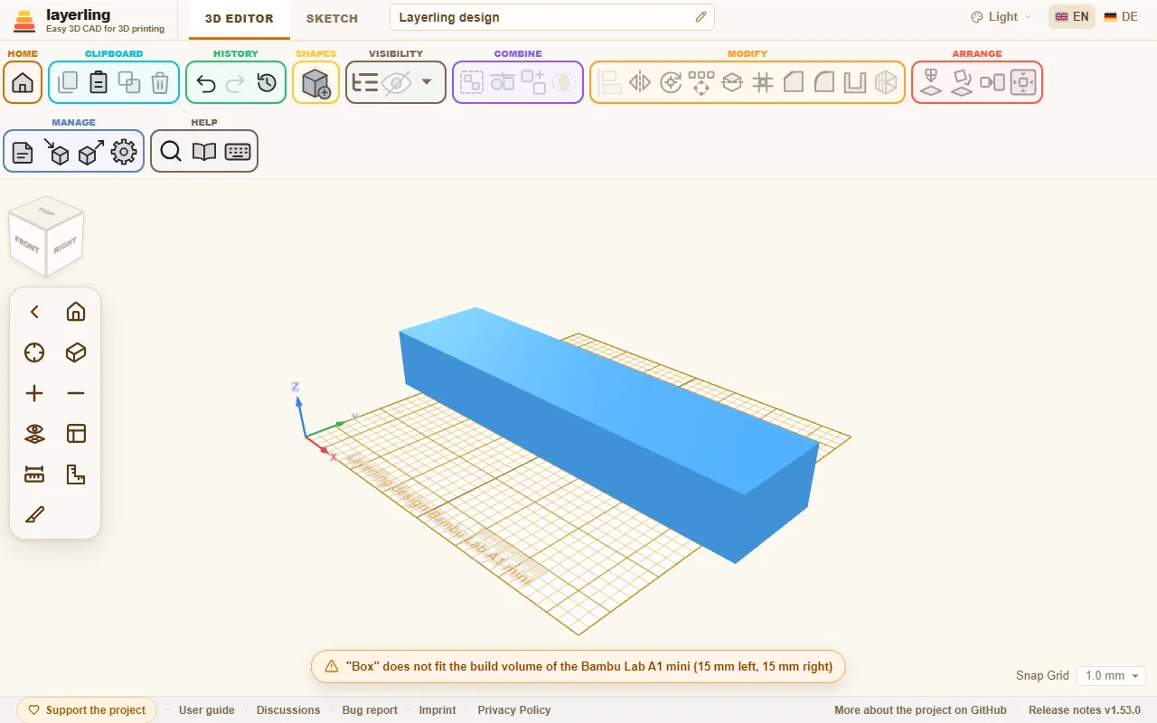
The warning does not stop you from working on. It is a hint so you do not find out only in the slicer that the part is too big. A part that is too big can often be split: cut it in two with “Split” and print both halves separately.
Laying the part right
How a part lies on the plate decides its strength and looks. Two tools in the “Arrange” area help:
- “Lay flat on face”: click a face and the part lies with that side down. The best print direction in one click.
- “Drop to workplane” (D): sets the part on the workplane when it floats somewhere in the air.
A few rules of thumb for direction:
- Large flat faces down. They stick best.
- Lay long, loaded parts so the layers do not run perpendicular to the load. Layers are the weakest direction.
- Avoid overhangs steeper than 45°, or give them supports in the slicer.
Finding overhangs
In the menu next to the eye (“Visibility”), Show overhangs switches the overhangs on. Every face that points down more steeply than 45° is then hatched red and white - that is where the printer would need supports. What rests on the plate stays clear. So you see while designing whether a sphere, an arch or a horizontal hole prints without supports; the teardrop hole is made for exactly that. Turn the part or lay it on another face with “Lay flat on face”, and the hatching follows at once.
How steep your printer manages is set in the settings under “Appearance”: from 30° (careful) to 70° (for printers with good part cooling). A face resting on another body is still marked - layerling only looks at the face itself.
Wall thickness, clearance and chamfers
- Walls should be at least two extrusion lines wide, so 0.8 mm with a 0.4 mm nozzle. Sturdy parts need 1.2 to 2 mm.
- Where two parts fit into each other you need clearance: usually 0.2 to 0.4 mm, depending on the printer. Make a small test pair before you print the big part.
- Many people lightly chamfer the lower edge that sits on the plate. That keeps the first layer from spreading ("elephant foot").
When you are ready
Choose “Export” and then STL or 3MF. STL is the simplest format. 3MF keeps names and colours of the individual bodies and is therefore handy when you print in several colours. The export window also shows how many grams and metres of filament the part would take printed solid. More in Files and saving.
12. Files, saving and sharing
Where your designs live, how to back them up, which formats layerling imports and exports, and what is possible on a shared server.
Where your designs live
layerling saves everything in the browser on your computer. There is no account and nothing is uploaded. Every change saves itself. The preview picture on the start page shows the view you last had in front of you when you went back with “Home dashboard”. If you open layerling in the same browser days later, everything is there.
If you go back to the start page from a design with nothing in it, layerling asks whether to keep it. “Yes” or Enter keeps it, “No” removes it, so empty designs do not pile up. Designs in a shared folder on a server are not asked about.
That has a downside: whoever clears the browser storage or switches to another computer loses the designs. So back up important work into a file.
Backing up and passing on
On the start page every design has a menu with the options to rename, duplicate and delete. With “Back up all” you pack all designs into one single file. Through “Open a design or import geometry” they come back, also in another browser or on another computer. The “Custom shapes” of this browser travel in the same file, in the folder Custom shapes, see Shapes.
You back up a single design in the editor: “Export”, choose the format LYL and click “Save layerling design”. The LYL file is layerling's own design format and contains everything: shapes, groups, sketches, CAD data, imported sources and the history, meaning the undo steps. Under “Saved action history” you choose how many of the last steps travel along; it starts at what the settings (the cogwheel in the ribbon) keep under “History”. The last stop, “None”, saves the design with its current state only - the way to share a file without its undo steps. The export is a copy under the “File name” you give it; the design in your browser keeps its history. Older .skf files from earlier versions can still be opened; they are then saved as .lyl.
Saving into your own folder (Chrome and Edge). There the button opens your system's save dialog, so you pick the folder and the name yourself, and an existing file can be replaced. Afterwards Ctrl+S saves the design into that same file again, without a dialog. A design opened from a .lyl file with “Open a design or import geometry” or the open button of the export window saves back into that file, too. The browser may ask once for permission to change the file. After the page is reloaded the design forgets its file, and the next Ctrl+S asks for it again; the dialog starts in the folder you used last. Firefox and Safari do not allow a page to write into files like this. There the file is downloaded to the Downloads folder as before, and Ctrl+S downloads it again; Firefox can be set to ask for the folder each time under Settings, General, Downloads.
Exporting
Click “Export” or press Ctrl+E.
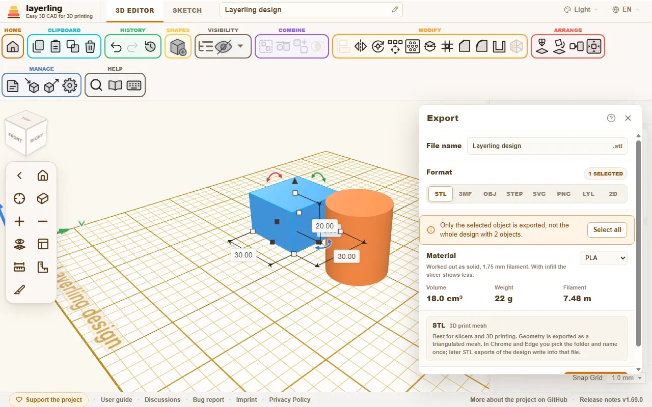
At the top is the file name, below it you choose the format. With something selected, only the selection is exported, otherwise the whole design. If the selection leaves out visible parts, a note in the window says so plainly, and “Select all” selects everything visible in one click. Once the file is written, the window closes by itself; if the export fails, it stays open with the message.
| Format | For | What to know |
|---|---|---|
| STL | slicer and 3D printing | A triangle mesh. The simplest and most widespread format. |
| 3MF | slicer with colours | Every body stays a part of its own with name and colour. Overlapping bodies are only joined when they share a colour; where a shape sits inside one of another colour, say a logo in a plate, the one built first leaves room for the later one. Suited to PrusaSlicer, Bambu Studio, OrcaSlicer and Cura. Bambu Studio and OrcaSlicer ask on opening how to map the colours onto your filaments, and call the file "not from Bambu" - the message is harmless. |
| OBJ | modelling and exchange | A widely supported mesh format. Colours are stored as vertex colours in the same file, with no extra .mtl. Bambu Studio and OrcaSlicer read them and ask, as with 3MF, how to map them onto your filaments; other programs see only the shape. As with 3MF, overlapping bodies are only joined when they share a colour. |
| STEP | a full CAD program | Keeps boxes, cylinders, spheres and cones as exact geometry, and so shapes made from an outline (star, heart, ellipse, tube, half sphere, round roof, rounded box, dovetail, the bores and more), the bent tube, threads, springs and gears, plus fillets and chamfers. The first STEP export in a session loads the CAD kernel (about 22 MB) once. |
| SVG | laser cutter and plotter | A clean top view in millimetres, including holes and curved outlines. |
| PNG | forum posts, print sites, questions | A picture of the view as it is, at twice the resolution and without handles, selection frames and dimensions. “Show the build plate” and “Transparent background” are chosen in the window. Turn and zoom first until the picture is right; the selection does not matter here. |
| LYL | layerling itself | The editable design with everything that belongs to it. |
| 2D | workshop, lathe and mill, documentation | A drawing at 1:1 as PDF or SVG: front, top and right-side views on an ISO sheet. See below. |
STL into your own folder (Chrome and Edge). There the first STL export of a design opens your system's save dialog, so you pick the folder and the name yourself and can replace an existing file. After that every STL export of the design writes into that same file without a dialog; the export window shows which file, and Save as… next to the export button picks another. The dialog remembers its own folder, apart from the one for designs, so the slicer files can stay with the slicer. After the page is reloaded the design forgets its STL file and the next export asks again. Firefox and Safari download the file as before.
A hole you have not grouped is taken out of every body it reaches when you export, as the view shows it. So there is no need to group before each export. With a selection, only the selected holes count. A hole cannot be exported on its own; layerling points that out.
STEP only carries exact CAD bodies. What cannot be written exactly, such as a mesh imported as STL, is left out. The message after the export names those bodies and says why. For the printer, use STL or 3MF, which carry everything.
A drawing for the workshop
Choose the format 2D (hover over it and it says Drawing) and, below the file name, PDF or SVG. With something selected, only the selection is drawn, otherwise the whole visible design; holes you have not grouped still cut the parts they reach.
layerling draws the front, top and right-side views in first-angle layout (the right side to the left of the front view, the top view below it) on the smallest ISO sheet that fits, from A4 to A0, or a larger one if the part needs it. It is always at 1:1. Each view carries its overall width and height, and edges you cannot see are dashed. Round bores that run parallel to a view direction get a centre cross and a label (F1, T1, R1), and a table at the bottom lists their diameter and position, measured from the lower-left corner of the view. The title block in the lower-right corner holds the name, scale, units, date and sheet number. The words on the sheet follow the interface language.
Print at 100 % or "actual size", or the lengths will not match. What the drawing does not do: threads, depths, tolerances and bores at an angle are not dimensioned, and the sizes come from the model as a mesh, so they are nominal. A very detailed part (over 100,000 triangles) or more than 200 bores is refused with a message; choose fewer objects then.
The projection is based on the drawing work of Cadverix-3D by WC3D.
How much filament does it take?
For STL, 3MF, OBJ and STEP the “Material” box shows the volume, weight and length of 1.75 mm filament of what is exported. It counts like the file: visible bodies only, holes taken off, overlaps only once. On the right you pick the filament - PLA, PETG, ABS, ASA, TPU or PA (nylon) - and the weight follows its density. The volume is the body's own. Weight and filament are a rough estimate for a print with walls and infill: you set the “Infill” (15 % to begin with) and the “Walls” (2) under the heading, and the box says what it counted and what the same part would weigh solid. Your slicer's own settings decide the real number, so take it as a guide: good for comparing designs and for whether the spool will last. At 100 % infill the box counts the part as solid, the upper bound.
Importing
With “Import” or Ctrl+I you bring foreign files into the design.
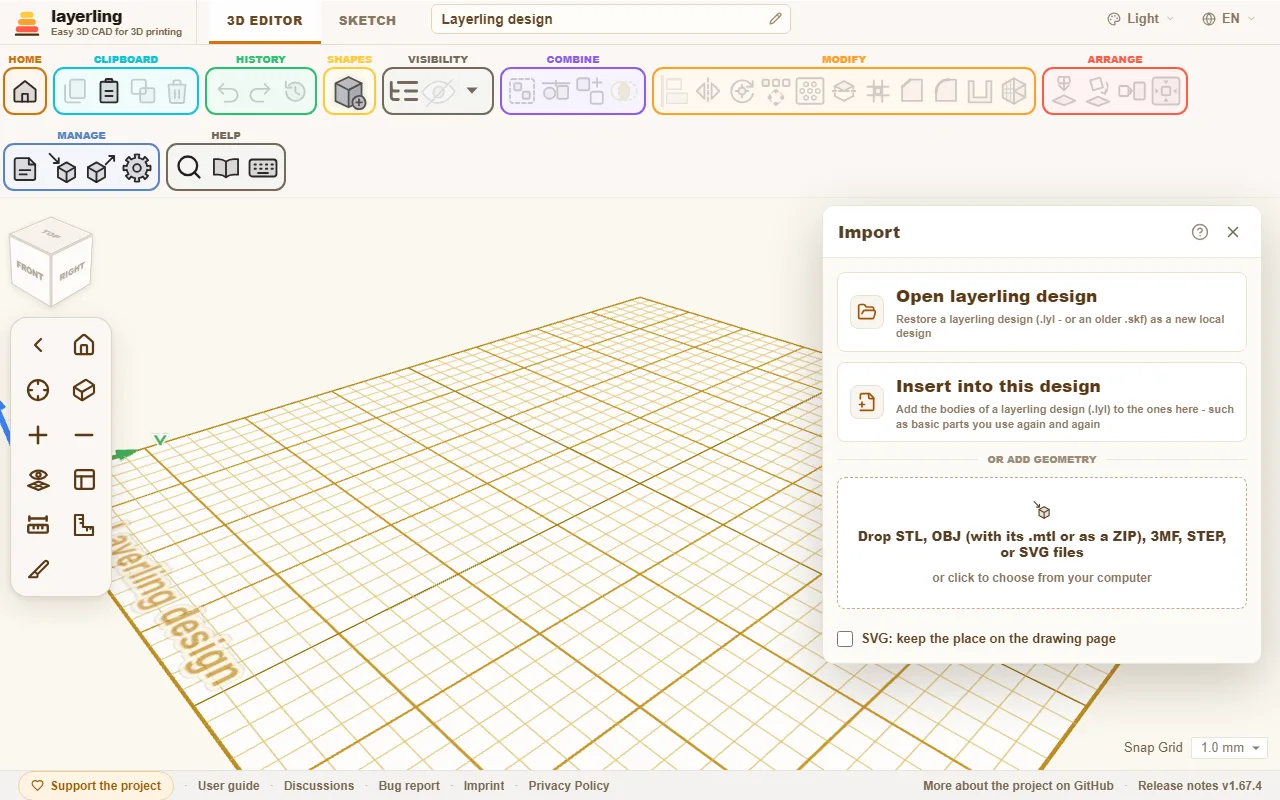
- “Open layerling design”: A layerling design (
.lyl, or an older.skf) comes back as a new design. - “Insert into this design”: The bodies of a layerling design are added to the open one. Handy for basic shapes you need again and again: build them once, save them and bring them in every time.
- Add geometry: Drop STL, OBJ, 3MF, STEP or SVG files in the window or click to choose a file. Imported meshes can be turned, moved, cut with holes and built upon. An SVG comes in as a sketch body, one from a tracer such as picsvg.com or Inkscape's "Trace Bitmap" as well: its outlines become the lines and curves of a sketch, 4 mm high and reading from above as in the drawing. In the properties you set its “Fill”, an area or a stroke outside, inside or centred, and “Silhouette (No Holes)” leaves the holes out, see Sketches, "Fill and silhouette". You change the points themselves in sketch mode. Only a very intricate SVG with more than 2500 lines and curves comes in as a fixed mesh. A shape that cannot be built into a solid, such as an outline that crosses itself or touches itself at a point, is left out, and after the import layerling says how many there were. Then it helps to join overlapping pieces in the drawing program, close the outlines and save the file again. Drawings made on one page, such as the layers of one document exported as separate files, line up again when you switch on “SVG: keep the place on the drawing page” in the import window before you import them: each keeps its place on the page, where otherwise each is centred on itself. A coloured OBJ or 3MF comes in as one body per colour, each in its place. In an OBJ the colours sit either in the file itself, as in an OBJ from layerling, or in an
.mtlbeside it. Select that one too, or import the whole ZIP the way Tinkercad hands out its OBJ. A 3MF carries its colours itself, and in a project from Bambu Studio, OrcaSlicer or PrusaSlicer each part takes the colour of its filament. A 3MF with several objects, such as a project with one object per plate, comes in as one body per object; modifiers, negative volumes and support blockers from the slicer are left out. Colour painted onto faces in the slicer is not read.
A design saved with a newer layerling may hold things your version does not know yet, such as a new shape, a new setting or fonts of one's own. If layerling cannot open it for that reason, the message names both versions. If it opens, the notice says that newer things may look different here. Either way, reloading the page helps: layerling.com always serves the newest version. The installed app picks it up the next time it starts; on your own server you install the update.
Template pictures are added in sketch mode, see Sketches.
Simplifying an imported mesh
A scanned or sculpted mesh often has far more triangles than its shape needs, and every one of them is carried along while you move, cut and save. “Simplify mesh” in the Modify group (or in the right-click menu of the body) shows the mesh as it is next to what a chosen share of its triangles would leave of it; both views turn and zoom together with the mouse buttons of the workplane. Set how much to keep as a percentage or a number of triangles, and “Simplify” takes the lighter mesh. The result is a plain mesh: for the result of a cut or merge, “Edit group” and its original parts are given up.
Cutting, merging and intersecting an imported mesh is calculated in your browser, so the workspace settings limit how many triangles such a mesh may have (“Cut imported meshes up to”). A mesh above the limit is not processed, and the message names its triangle count; simplify the mesh first, or raise the limit if your computer can take it.
Reporting a bug
If layerling does something unexpected, save a “Bug report”: the link sits in the footer at the bottom, next to the forum. It is a ZIP file, because GitHub and many forums refuse a bare .lyl: inside are your design as a .lyl and a short text file with the version, browser, screen size, the last messages and any errors. The start page opens the ZIP like a backup, or you unpack it and open the .lyl. Nothing personal is in it. Attach the file to your post in the forum or on GitHub, so the problem can be followed with exactly your design.
If layerling stops with an error, a window with the error message shows instead of a blank page. From it you can save the state of the design last stored in the browser as a .lyl file, go back to the overview, or start a new design. The error message from the window and the saved file help when you report it.
Shared designs on a server
When layerling runs on your own computer or web server, it can offer a shared folder in which all users keep designs. On the start page it then appears as “On the server”. You create folders there, move designs by dragging and search across the whole folder. A design that lives there saves itself back to it. A design from this browser goes onto the server by dragging its card onto the server tile, or with “Put on the server” in the card's menu. A backup you open lands in this browser first, like any design you open; put the designs on the server from there. The start page shows a design by its file name, so renaming a design, on its card or at the top of the editor, renames the file on the server too. Deleting a design or a folder removes it for good, together with its working copy in this browser. Custom shapes kept on the server sit in its folder Custom shapes, see Shapes.
Two things make that quicker: “Put all on the server” on the start page puts every design of this browser on the server in one go, and ticking “New designs on the server” makes every new design start in the server folder, so it is saved there from the first change on. The tick is kept in this browser. A design that cannot go - its name is taken on the server, say - stays in the browser, and the message says how many.
That is not simultaneous editing: whoever opens a file works on a copy of their own. If somebody else has changed the file in the meantime, layerling refuses to overwrite it.
On layerling.com this function is not switched on. How to set it up on your own server is described in the README on GitHub.
13. Keyboard shortcuts
All keys at a glance, taken straight from the program so the list is always right.
The shortcuts work as long as the workplane has the focus. While you type in a field they keep out of the way. On the Mac, Cmd applies wherever Ctrl is listed here.
In the editor, “Keyboard shortcuts” in the “Help” area opens the same list as a window.
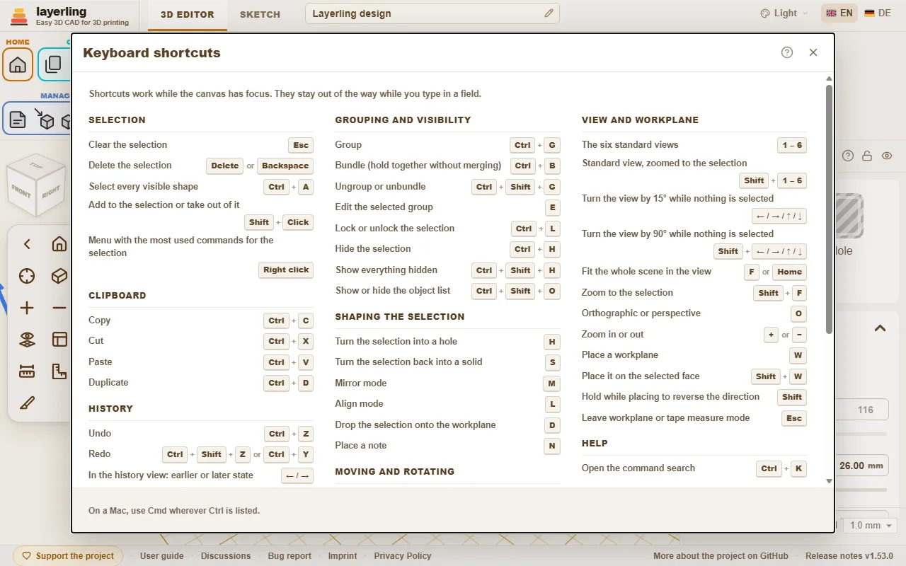
Command search
Can't find a tool? Press Ctrl+K or click the magnifying glass in the “Help” area, then type what you are looking for: a tool ("fillet", "mirror"), a shape ("cylinder") or a command ("export", "undo"). Move with the arrow keys and press Enter, or click the entry.
- The search understands the English and the German word alike and ignores capital letters and umlauts: "aushoehlen" finds “Hollow”.
- Every entry shows the keys that do the same and the area of the toolbar it lives in, so you learn where it is.
- Entries that are greyed out cannot run right now, mostly because nothing is selected. They stay in the list so the search still tells you where the tool is.
The guide you are reading has a search box too, at the top of every page: type a word or two and it lists the sections that contain all of them, with the matching words marked. Click one, or press Enter for the first, to jump straight there.
- A shape's name adds that shape to the workplane, just like clicking it in the shapes menu.
- With an empty field the search lists the commands you used last at the top.
- The name of a body in your design finds that body and selects it, which helps in a design with many parts. Bodies only appear once you type.
- It works in sketch mode as well, with the sketch tools.
Selection
| Esc | Clear the selection |
| Delete or Backspace | Delete the selection |
| Ctrl+A | Select every visible shape |
| Shift+Click | Add to the selection or take out of it |
| Right click | Menu with the most used commands for the selection |
Clipboard
| Ctrl+C | Copy |
| Ctrl+X | Cut |
| Ctrl+V | Paste |
| Ctrl+D | Duplicate |
History
| Ctrl+Z | Undo |
| Ctrl+Shift+Z or Ctrl+Y | Redo |
| ← / → | In the history view: earlier or later state |
| Esc | In the history view: back to the current state |
File
| Ctrl+I | Open or close the import dialog |
| Ctrl+E | Open or close the export dialog |
| Ctrl+S | Save the design into its file |
Grouping and visibility
| Ctrl+G | Group |
| Ctrl+B | Bundle (hold together without merging) |
| Ctrl+Shift+G | Ungroup or unbundle |
| E | Edit the selected group |
| Ctrl+L | Lock or unlock the selection |
| Ctrl+H | Hide the selection |
| Ctrl+Shift+H | Show everything hidden |
| Ctrl+Shift+O | Show or hide the object list |
Shaping the selection
| H | Turn the selection into a hole |
| S | Turn the selection back into a solid |
| T | Make the selection see-through, or opaque again |
| M | Mirror mode |
| B | Fillet tool for the selected body (again: close it) |
| Shift+B | Chamfer tool for the selected body (again: close it) |
| L | Align mode |
| D | Drop the selection onto the workplane |
| C | Pick up the selection and set it down on a face (like Cruise in Tinkercad) |
| N | Place a note |
Moving and rotating
| ← / → / ↑ / ↓ | Move by one grid step, as the view is turned |
| Shift+← / → / ↑ / ↓ | Move by five grid steps |
| Ctrl+↑ / ↓ | Raise or lower the selection |
| R | Rotate by 45° |
| Shift+R | Rotate by 22.5° |
| Shift | Hold while dragging: move along X or Y only |
| Alt+Drag | Drag a copy, the original stays put |
| Alt | Pressed once dragging: pause snapping to other shapes |
View and workplane
| 1 – 6 | The six standard views |
| Shift+1 – 6 | Standard view, zoomed to the selection |
| ← / → / ↑ / ↓ | Turn the view by 15° while nothing is selected |
| Shift+← / → / ↑ / ↓ | Turn the view by 90° while nothing is selected |
| F or Home | Fit the whole scene in the view |
| Shift+F | Zoom to the selection |
| O | Orthographic or perspective |
| + or − | Zoom in or out |
| W | Place a workplane |
| Shift+W | Place it on the selected face |
| Shift | Hold while placing to reverse the direction |
| Esc | Leave workplane or tape measure mode |
Help
| Ctrl+K | Open the command search |
Sketch mode
| Ctrl+K | Open the command search |
| Esc | End the chain, clear the selection |
| Delete or Backspace | Delete the selected element |
| Ctrl+C | Copy |
| Ctrl+X | Cut |
| Ctrl+V | Paste |
| Ctrl+D | Duplicate |
| Ctrl+Z | Undo |
| Ctrl+Shift+Z or Ctrl+Y | Redo |
| R | Rotate a closed sketch by 45° |
| L | Lock or unlock the reference image |
| F or Home | Fit the whole sketch in the view |
| Shift+F | Zoom to the selection in the sketch |
| + or − | Zoom in or out of the sketch |
| Alt+Enter | In a line's length field: grow to both sides |
| ← / → / ↑ / ↓ or Shift+← / → / ↑ / ↓ | Move the selected points, lines or image by one grid step (Shift: a larger step) |
| Shift | While drawing: snap the new line in 15° steps |
| Shift | While dragging: keep the move on one axis |
| 0-9 or < or Tab or Enter | While drawing: type the length, "<" or Tab for the angle, Enter sets the point |
Chamfer and fillet
| Enter | Apply the preview |
| Esc | Discard the preview |
14. Building with an AI (MCP)
How an AI assistant such as Claude or Codex creates and changes shapes, groups them and takes pictures of the view in your open editor.
layerling comes with an MCP server. MCP is a standard through which an AI assistant can use tools in other programs. With it an AI client such as Claude or Codex sees an open editor tab and works in it: it creates shapes, changes dimensions, groups, cuts, rounds edges, reads out the scene and takes pictures of the view. You describe the part, the AI builds it, you watch and can step in at any moment.
The bridge between AI client and editor runs locally on your computer. Keep in mind, though: what the AI reads, meaning the scene and the pictures of the view, goes to the provider of your AI client, like any other input there.
Setting up
- Get layerling from GitHub and start it in the project folder with
npm run dev. Node.js must be installed. On Windows the quick-start line in the README takes care of that. - Open an editor tab, for example
http://127.0.0.1:3000/?editor=1. You can leave that to the AI: when no editor is open, the first tool that needs one starts your browser with an editor and waits until it has connected. That works for a layerling on your own computer; a copy on a NAS or server needs you to open the editor. SetLAYERLING_MCP_OPEN_EDITOR=0for the MCP server to switch it off. - Connect your AI client to the MCP server. The client starts it itself with
node scripts/layerling-mcp-server.mjs.
Claude Code
Nothing to install: the project brings a .mcp.json that registers the server, and the skill under .claude/skills/layerling-mcp-skill. Open the layerling folder in Claude Code and ask, for example: "Use the layerling MCP tools to list my open editors and inspect the scene."
Claude Desktop
Claude Desktop does not read project files. Enter the server in its own configuration. As a template use docs/mcp/claude-desktop-config.example.json in the project, replacing the script path with the absolute path on your computer. Then restart Claude Desktop.
Codex
Copy the skill from docs/skills/layerling-mcp-skill into your Codex skills folder, enter the server in your Codex configuration using docs/mcp/codex-config.example.toml, and restart Codex.
The detailed instructions for all three are in the README on GitHub.
A copy on a NAS or server
A copy you host yourself can let an AI client drive its open editors over the network. It is off by default, because whoever can drive the bridge can read and change the open designs. On the server, set LAYERLING_MCP_REMOTE to true and LAYERLING_MCP_TOKEN to a secret of at least 16 characters (for the Docker image in environment: of the compose file; no rebuild needed). Open an editor tab of that copy and keep it open, and give the MCP client the address and the same token: LAYERLING_URL=http://nas:3000 and LAYERLING_MCP_TOKEN=<the token>.
Only a client with the token can list or drive the editors. The editor pages need none, but they only count under an address or name that only your own network can use (an IP address, a name without a dot, or one ending in .local or .lan); a real domain behind a reverse proxy goes into LAYERLING_MCP_ALLOWED_HOSTS. Use it on a network you trust, and HTTPS beyond it. The README has the details.
What the AI can do
The AI works with the same functions as you, through the same path as your operation in the editor. New layerling functions get their MCP action right away. The tools:
| Tool | What it does |
|---|---|
layerling_list_editors | lists the open editor tabs |
layerling_open_editor | opens a new editor tab in your default browser and waits until it has connected (on your own computer only) |
layerling_read_scene | reads scene, selection, units and the exact dimensions of all objects |
layerling_list_objects | lists all objects with dimensions, position, rotation and id |
layerling_select_objects | selects objects |
layerling_delete_objects | deletes objects |
layerling_create_shape | creates a shape: box, cylinder, text (also curved), thread, gear, sketch body and all the others |
layerling_import_file | imports a file as the import window does, a coloured OBJ or 3MF as one body per colour, a 3MF with several objects as one body per object |
layerling_add_font | adds a font of one's own for text from a TrueType, OpenType or WOFF file; it stays in the browser, a design keeps only the letters it uses |
layerling_list_fonts | lists the built-in fonts and the fonts of one's own, with id and name |
layerling_import_mesh | brings a triangle mesh into the design |
layerling_update_object | changes dimensions, position, colour, name, solid or hole and everything else that makes up the shape, a text's letter edge included |
layerling_align_objects | aligns objects with each other |
layerling_scale_objects | scales objects by a percentage, together or each in place |
layerling_lay_flat | lays an object with one face on the plate |
layerling_place_on_face | sets objects down on a face of another, sloped ones too, like the C key |
layerling_perforate_face | cuts a hole pattern into a flat face; the holes stay as holes grouped with the body |
layerling_mate_faces | brings a face of one object against a face of another, face to face or flush |
layerling_open_group | opens a group so its parts can be changed one by one, also a group inside an open one |
layerling_close_group | closes it again ("Done") or cancels |
layerling_group_objects | groups objects |
layerling_ungroup_objects | dissolves groups |
layerling_boolean_cut | cuts solids with holes |
layerling_intersect_objects | keeps only what the objects have in common (Intersection) |
layerling_separate_parts | separates a shape into its loose parts |
layerling_split_objects | cuts solids or holes in two with a plane |
layerling_list_edges | lists the real CAD edges of an object |
layerling_apply_edge_treatment | chamfers or fillets chosen edges |
layerling_hollow_object | hollows a body with an even wall |
layerling_array_objects | multiplies in a row or on a circle |
layerling_bundle_objects | bundles objects like Ctrl+B: they move together, keep their colour and kind and go out separately in an export |
layerling_layer_text | turns a text into a stack of layers for a multicolour print (letters, wider rims, a plate without holes) or builds a stack again, with a key ring hole, the corners per layer and a rounded or chamfered letter edge; with a name list, one tag per name |
layerling_layer_icon | turns an SVG icon (the text of the file, or an extruded sketch body) into a layered icon tag for a multicolour print - the icon, wider rims, a plate without holes - or builds one again with a new width or layers; with a count it fills the plate with copies |
layerling_measure_section | measures on a cutting plane between two points that snap to the outline - wall thickness, gaps, fits |
layerling_show_overhangs | switches the overhang hatching on or off, sets the angle and reports for each body the area that would need supports |
layerling_estimate_print | estimates volume, weight and filament for the selection or the whole design: for a solid body, and as a rough guess with walls and infill like the export window |
layerling_add_reference_points | marks reference points - on the centre, corners or edge middles of objects, or at exact positions - that shapes snap to |
layerling_list_reference_points | lists the reference points with their ids and positions |
layerling_remove_reference_points | deletes reference points by id, or all of them |
layerling_inspect_errors | shows the last message and the last error, plus the messages and errors of the session |
layerling_wrap_around_cylinder | wraps a body lying flat, an SVG or text for example, around a cylinder, outward or inward as an engraving |
layerling_simplify_mesh | reduces the triangle count of an imported mesh, to a share in percent or to a number of triangles |
layerling_save_custom_shape | keeps bodies as a custom shape, on the server or in the browser, to insert them into other designs |
layerling_list_custom_shapes | lists the custom shapes on the server and in the browser |
layerling_insert_custom_shape | inserts a custom shape into the open design, at a spot x/z if you like |
layerling_delete_custom_shape | removes a custom shape; inserted bodies stay |
layerling_show_workplane | hides and shows the plate with its grid, for a picture of the underside for example (only the view) |
layerling_set_section_view | cuts the view open along a plane to look inside (only the view, nothing is cut apart) |
layerling_clear_history | deletes every undo step for good, as the History view's "Delete history" button does; needs confirm: true |
layerling_set_history_view | looks back at an earlier state of the project, like the History view (the real design stays untouched; changing tools wait until it is closed) |
layerling_export_section_svg | returns the outlines on a cutting plane as an SVG at 1:1, from the same bodies as the export |
layerling_export_drawing | makes the workshop drawing of the "2D" export: three views at 1:1 on an ISO sheet with overall sizes and a table of the round bores, as SVG text or PDF |
layerling_set_workplane | puts the workplane on a side of a body or back on the base plate, and hides or shows it |
layerling_capture_image | takes a picture of the view: front, top, side, diagonally from a corner and more |
That lets the AI check itself: it creates something, takes a picture, looks and improves.
An example
You say: "Build me a round box 60 mm across, 40 mm high with a 2.5 mm wall, open at the top, plus a flat lid with 'Tea' written in an arc." The AI creates the cylinders, hollows one, puts the curved text on the lid and takes pictures at the end to see whether it fits.
15. Installing as an app, working offline and self-hosting
Start layerling like a normal program, even without a network, and how to run it on your own computer.
Installing as an app
layerling can be installed like a normal program. It then gets an icon and a window of its own, without an address bar. After the first visit it starts even without internet. Your designs stay on your computer.
On the start page a hint with “Install now” appears if your browser can do it. Otherwise:
- Chrome and Edge: Click the install icon at the right of the address bar, or choose "Install as app" in the browser menu.
- Safari on the Mac: Menu "File", then "Add to Dock".
- Safari on iPhone and iPad: Share icon, then "Add to Home Screen".
- Firefox: cannot install apps. layerling still starts offline in a tab there.
You can close the hint on the start page with “Hide this hint”. Starting the installed app a second time in Chrome or Edge brings the open window to the front instead of opening another one.
Updates
When a newer version exists, layerling shows it on the start page. Through “Release notes & download” you read what has changed. The version number is at the bottom right. After reloading the page you have the new version.
On layerling.com and on other web servers an open page notices an update by itself. It asks the server for its version now and then, when you come back to the tab, and at once if a program file it needs has disappeared. When something new was installed in the meantime, a card at the bottom right says so and lists what is new. “Save and reload” writes the design you have open into the browser first and then loads the page again; the design comes back as you left it. “Later” holds the card back for 15 minutes. Reload soon: a page that stays on the old version may load parts of the new one that do not fit. The same card appears when that has already happened: the CAD workers, which load only when you first need them, say which build they are from, and if it is not the page's own - after an update, or with a stored copy of an older version - the card asks for a reload before the two misunderstand each other.
When layerling is open in several tabs, they look out for each other: if another tab already runs a newer version, a note at the bottom of the old tab asks you to reload it. And if the same design is open in two tabs, both warn you, because they save automatically and would overwrite each other. If you open layerling in one more tab while one is already open, the new tab suggests carrying on in the old one and offers to close itself. If you want two tabs on purpose, say for two designs side by side, click “Keep working here” there. This guide opens in a tab of its own as well: while layerling is open next to it, its button at the top right reads "Back to the editor" and closes the guide instead of opening the editor a second time.
Language and appearance
You set the language at the top right, German or English. The colour scheme beside it offers “System” (follows the operating system), “Light”, “Dark” and “Graphite”, a neutral dark grey.
Running it yourself
layerling is free software (AGPL-3.0) and can be run on your own computer or server, for example in a workshop, a club or a school. There are several ways, described in the README on GitHub:
- The quick start on Windows: A single line in PowerShell installs everything and puts a shortcut on the desktop. When layerling is already running, another double-click starts no second server and only opens the page.
- Docker: For NAS devices and home servers, without Node.js needing to be installed. Every release comes as a ready-made image
henmedia/layerlingon Docker Hub (alsoghcr.io/henmedia/layerling) for amd64 and arm64;docker run -d -p 3000:3000 henmedia/layerling:lateststarts it, and on a NAS you search for it in the container manager's registry. - Static export: The result is plain files that any web server can serve. They belong at the root of an address (
https://layerling.example.com/orhttp://192.168.0.5:8080/), not in a subfolder and not opened from disk; the README has the steps. With a writable folderstorenext toindex.htmland PHP on the server it also becomes the shared storage for designs.
The MCP bridge for AI assistants exists only in the development server, see Building with an AI.
Help and feedback
- In the editor, the “Help” area holds the “Quick guide” with the most important moves and the overview of keyboard shortcuts. Each section of the quick guide has a question mark that leads to the matching chapter here.

16. Videos about layerling
Videos that other people have made about layerling.
Made by others
These videos are not from this project. The links open YouTube in a new tab; nothing is loaded from there until you click.
- The PERFECT FREE CAD Program Between Tinkercad and Fusion 360! – Print N Repeat (English). A video about layerling as a free CAD program between Tinkercad and Fusion 360.
- Meet Layerling Free Browser Based CAD that EXTENDS Tinkercad! – HL ModTech (English). A look at layerling by a Tinkercad user, about 23 minutes: free, browser-based CAD that extends Tinkercad.
- Layerling – Playlist – Making Layers (English). A series about layerling, so far with "Tinkercad alternative / upgrade? Introducing Layerling!", an overview for people coming from Tinkercad, and "Layerling Sketch Tools!" on the sketch tools.
- Tinkercad Too Basic? Fusion 360 Too Much? Meet Layerling for 3D Printing – 3D Jesus | 3D Printing & Design (English). A first test of layerling without any manual: fillets and chamfers, hollowing, threads, sketches, revolved bodies, patterns, import and printer profiles.
Do you know another video, or made one yourself? Tell us in the discussions and it will be added here.