
View and workplane
Moving around the scene, looking straight on, and placing new shapes on any surface you like.
Moving around
With the mouse:
| What you do | What happens |
|---|---|
| drag with the right button | rotate the view |
| click the right button | on a body, a menu with the most used commands: duplicate, hole or solid, group, hide, lock, delete and more; on empty space Paste and Select all |
| drag with the middle button | move the view |
| mouse wheel | zoom in and out |
| hold Ctrl and drag with the left button | also moves the view |
On a tablet or phone, two fingers zoom (spread and pinch) and move the view (slide together). One finger works on the design, just like the left mouse button. To rotate with one finger, switch on “Rotate the view with one finger” in the camera bar. That switch only shows on devices with a touch screen.
A graphics tablet with a pen behaves like a mouse: the tip is the left button, the barrel button on the pen the right one, for turning the view and for the menu. The tablet's hotkeys can be set in its driver to layerling's keyboard shortcuts.
The view cube
The cube in the top left shows where you are looking. A click on one of its sides jumps to the straight view from top, bottom, front, back, left or right. A click on a corner of the cube looks at the model diagonally from that corner, and a click near an edge looks from that edge, between two sides; the spot lights up while the pointer is on it. The number keys 1 to 6 give the straight views too. Hold Shift with them and the view also zooms to the selection, as Shift+F does.
Drag the cube to turn the view around, just like dragging with the right mouse button. With nothing selected, the arrow keys turn the view as well: 15° a press, 90° with Shift. They turn the model the way they point - → turns its front to the right, ↑ tilts its front upwards. If something is selected, the arrows move it; click on empty space first to turn the view. On a touch screen this works with one finger, without switching on “Rotate the view with one finger”.
The camera bar
At the left edge is a narrow bar. From the top:
- “Home” brings the whole scene back into view. The key is F or Home.
- “Center view on selection” zooms to the selection (Shift+F).
- “Zoom in” and “Zoom out” zoom step by step, as do the keys + and −.
- “Orthographic view” switches to a flat view in which parallel edges stay parallel. For measuring and lining up edges that is often more comfortable than the perspective view. O switches back and forth, and a second click returns.
- “Hide workplane” (the eye over a grid) hides the plate with its grid, so you can look at the underside of a design from below. Only the view changes: new shapes still land on the workplane. A second click shows it again.
- “Place workplane”, the tape measure and the framing square are tools of their own, covered below and in Measuring and notes.
The small arrow at the very top of the bar hides it if it gets in the way.
A design opens the way you left it: the angle, zoom and position of the view are kept with it in this browser, so you continue where you stopped, also after going Home or closing the page. A saved file (.lyl) carries the view along, so it opens in it elsewhere too. The view is not part of the undo history.
Looking inside: the section view
“Section view”, the last button in the bar (the cut tool), cuts the view open along a plane so you can check walls, cavities and parts that fit into each other. Nothing is cut for real: the design, its files and every export stay whole.
- Choose the axis the plane stands across: X (width), Y (depth) or Z (height), as in the position fields. The plane starts in the middle of your design.
- “Coarse” moves the plane across the whole design, “Fine” moves it a little either side of where it stands, for tenths of a millimetre. You can also type the position.
- The button beside the axes shows the other side of the cut, “Center” puts the plane back in the middle, and “Show cutting plane” hides the blue plane.
- You can click and select what the cut lays open, inner walls included.
- “Workplane here” puts the workplane on the cut. It lies on the plane of the section and faces out of the body that stays, like the face a cut leaves. If you then switch to the sketch, it starts exactly there, and the faint outline shows the cut, which you can draw along and snap to. That is how you sketch a lid that fits the cavity you opened with the section, for example. The button beside the axes chooses which side stays, and with it which way the workplane faces. You put the workplane back on the base plate as usual.
- “Measure” measures right on the cut: the outline shows in blue, and two clicks on it give the distance, plus its parts along the plane's two axes. Both points snap to the outline, corners first. When the second click lands anywhere on the opposite wall, it snaps square to the first point - so you read wall thickness, gaps and clearance without aiming exactly. A third click starts the next measurement, Esc ends measuring. Moving the plane clears the measurement.
- “Section as SVG” saves the outlines on the cutting plane as an SVG at 1:1, for a laser, a plotter, a template or a gasket. An X cut is seen from the right, a Y cut from the front, a Z cut from above. As in the export, only visible bodies go in, holes are already taken off, and bodies of the same colour are joined into one outline. Each colour stays its own path without a fill, so laser software keeps them apart as layers.
The panel hangs on its button. If it covers something, drag it by its title bar anywhere on the workplane; it opens there next time too. Double-click the title bar or drop it at the button to put it back.
Esc closes the panel; the cut stays until you switch it off or go back to the design overview. While it is on, its button stays highlighted. Anything you place on the side that is cut away only shows once you switch the cut off.
The workplane
New shapes align with the workplane. At first that is the base plate with the grid. But you can put it on any surface, to place something on a side or a sloped face.
- Press W or click “Place workplane”.
- Move the mouse over a face of a body. It lights up.
- A click puts the workplane there. Everything you add now sits on that face.
Click on the empty plate instead, and the workplane lies flat at the spot you clicked, on the snap grid. New shapes and a finished sketch, a revolved one too, then appear there rather than in the middle of the plate. While the workplane lies flat on the plate like this, the plate shows only its outline: two grids in the same plane would make a flickering pattern.
On a face the origin of the workplane otherwise snaps to the grid. Click close to a corner of the face and it sits exactly on that corner. Close to an edge it lies on the edge, and the grid lines up with it; that is how you choose the angle of the grid on purpose. Without a corner or an edge, the grid on a lying face runs parallel to the body, so on a turned box it is turned with it.
A click beside the plate or Esc returns the workplane to the base plate. Quicker still is “Workplane back to the base plate”: the button with the downward arrow sits in the camera bar below the eye while the workplane lies on a face. Shift+W puts it directly on the currently selected face. If you hold Shift while clicking, the plane points the other way.
While a workplane sits on a face, an eye appears next to “Place workplane”. It hides the workplane without dropping it, for a clear look at the design: new shapes still land on that face, and rotating still turns about it. A click on the eye shows it again, and so does setting a new workplane.
Grid and snapping
The grid shows the size of the plate. At the bottom right is the snap step: moving and scaling snap in steps of that size, for example 1 mm. Make it smaller for fine work and larger for rough arranging. “Snap to grid” in the ribbon moves the selected shapes afterwards onto the nearest grid crossing. While moving, shapes also snap to other shapes, see Selecting and arranging.
Under “Measurement” in the settings you set the “Units”. With “Imperial”, layerling shows every measure in inches, on the shape, in the properties panel, on the tape measure and the ruler. The snap grid then offers steps from 1/64 to 1 inch, and the grid on the plate is drawn in inches (1/8 to 1 inch, 1/4 inch by default) with a stronger line on every whole inch. Under “Show inches as” you choose whether inches appear as fractions like in Tinkercad (1 5/8, rounded to 1/64 inch) or as decimals (1.625) with as many decimal places as set under “Accuracy”. You can type either, "1 5/8" included.
Under “Custom snap grids” in the same place you add snap steps of your own: a name and a size in millimetres, for example "Pin pitch 2.54 mm" for the spacing of DIP chips, pin headers and perfboard holes, or "MX Key Unit" with 19.05 mm for the spacing of keyboard keys. The snap step menu then offers that measure whole, halved and quartered (1 ×, ½ × and ¼ ×), so shapes can be moved by one pitch, half a pitch or a quarter pitch. Custom steps are kept with the design and go along with “Make default”.
Size, grid width and colour of the plate are changed in the settings (the cogwheel in the ribbon): the areas are “Appearance”, “Measurement”, “Workplane”, “Shape defaults” and “History”. Under “Appearance” you find switches such as “Start editor in perspective view” and “Show shadows”, under “Workplane” “Show grid”. The colours of the work area are set under “Appearance” too: “Window background (light theme)” and “Workplane under the grid (light theme)” for the light theme (the dark themes keep their own), next to the grid colour under “Workplane”. There you also choose whether the darker grid line comes every 5 or every 10 grid steps (“Darker grid line every”) and give it a colour of its own with “Darker line color”; the centre cross and the plate border take it too. Every line of the grid grows wider as you zoom in, as in Tinkercad, and stays visible as you zoom out; if that is too much for you, switch off “Grid lines grow when zooming” and the lines stay one pixel wide at every zoom, as in the sketch. In the colour field, Enter takes a typed hex value. “Edge lines on all bodies” draws an outline on every body, in the colour of “Edge line color” (black to begin with, as in Tinkercad): it helps when dark colours run into each other. It is off by default, and very large imported meshes are left out. The grid always runs through the origin, so the stronger lines lie on the axes whatever the plate measures.
“Axis arrows” (on by default) draws three arrows at the back left corner of the plate: X in red to the right, Y in green to the back and Z in blue upwards, the way the position fields count. That is the right-hand rule Tinkercad, CAD programs and the slicers use too. With the workplane on a face they follow it. Switch them off here if they are in your way.
Two sliders under “Appearance” set how the bodies are lit. “Shadow strength” says how dark the cast shadows are, and “Shading contrast” moves light from the even ambient light to the main light: towards "punchy" the shaded sides get darker and the shadows show more, towards "soft" everything gets flatter. At the top end the contrast gets very strong, so shaded sides and shadows turn really dark. “Shadow softness” makes the edges of the shadows soft instead of crisp. “Light direction” turns the main light round the plate (0° from the front, 90° from the right), and “Light height” lifts it; at 90° it stands straight above the plate as in Tinkercad, and the shadows fall right under the bodies. “Reset light and shadows” puts everything back. “Classic look” sets the work area up as Tinkercad shows it: white ground, a pale blue millimetre grid with a darker line every centimetre, black edge lines, light from above with soft shadows. Every value can still be changed on its own afterwards. All of them start as layerling always looked, and what suits you depends on your monitor. The sketch view has its own colours: “Sketch: window background (light theme)” for the window round the sheet, “Sketch: area under the grid (light theme)” for the sheet under the grid, and “Sketch: grid color (light theme)”, all for the light theme. “Sketch like work area” takes over the work area's three colours in one click.
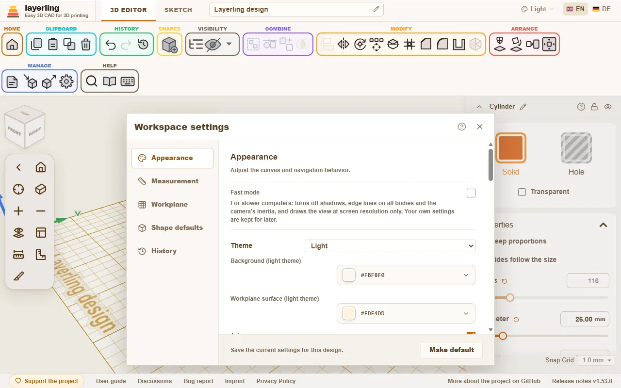
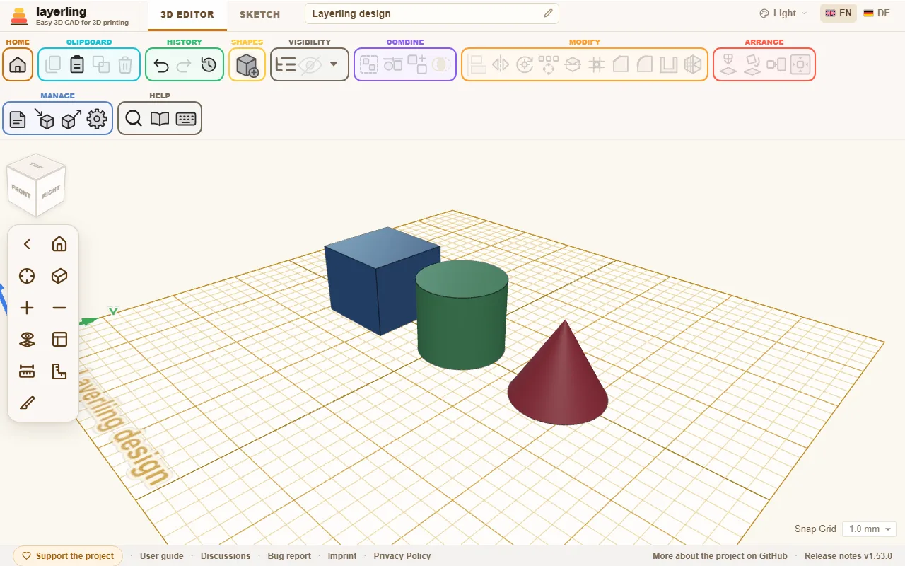
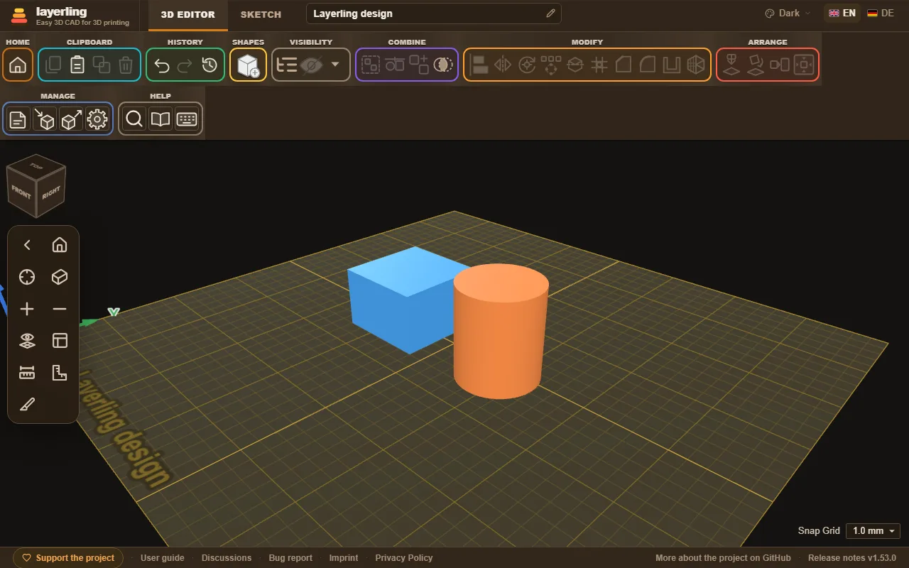
“Toolbar size” under “Appearance” makes the buttons of the ribbon on top, its shape menu and the camera controls on the left smaller or larger: “Small”, “Medium” (as it always was) or “Large”. Small leaves more room for the workplane on a laptop; large is easier to hit on a big screen or with a finger. With large buttons the groups of the ribbon go onto a second row when the window is too narrow for them. The size is kept in this browser and holds for every design.
When layerling feels slow
layerling calculates and draws everything in your browser. On an older computer, with a weak graphics card or on several large screens the view can therefore feel sluggish. This helps:
- “Fast mode” under “Appearance” turns off at once everything that costs the view a lot: shadows, edge lines on all bodies and the camera's inertia. It also draws the view at the screen's own resolution only, which on high-resolution screens is up to four times fewer pixels. Your own settings are kept and apply again as soon as you turn it off.
- The camera keeps turning: When you let go of the mouse after turning, the view turns on for a moment and slows down gently. That is on purpose, not stutter. If you are used to Tinkercad or Fusion 360, turn off “Camera keeps turning” under “Appearance”, and the view stops at once.
- Single switches: Without fast mode you can also turn off just “Show shadows” or “Edge lines on all bodies”.
- Use the graphics card: In Chrome open
chrome://gpu(in Edgeedge://gpu). Next to "WebGL" it should say "Hardware accelerated". If it says "Software only", hardware acceleration is off in the browser's settings. On Windows you can also pick "High performance" for the browser under Settings → System → Display → Graphics, so it uses the real graphics card and not the weaker one in the processor. - Simplify large imported meshes: A model of many hundred thousand triangles slows any view down. How to thin it out is in the chapter on files, under "Simplifying an imported mesh".
- Close other tabs: Every open layerling tab and every other 3D page shares the same graphics card.