
Placing and adjusting shapes
The shape library, dimensions by number and by handle, colour, rotating, tapering and twisting.
Every part in layerling starts with a shape. From them you build everything else: shapes complement each other, cut each other out or are joined into a new shape.
Adding a shape
Click “Add shape” in the ribbon. The shape library opens.

Pick a shape. It now hangs on the mouse pointer and lands where you click. Move it over a body and it lies down on the face under the pointer, sloped ones too, like Cruise in Tinkercad; over the empty plate it lands on the workplane. Esc cancels placing. A tool that waits for a click, such as the tape measure, the framing square, a note, “Place workplane”, “Lay flat on face” or the edge tools, is switched off when you pick a shape, so the click places the shape. The other way round, switching one of those tools on puts the shape down again. If you would rather have the shape appear in the middle of the plate, you can switch off placing by click in the settings (area “Appearance”, switch “Cruise when adding new shapes”).
What the library offers:
- Basic shapes: “Box”, “Rounded Box”, “Cylinder”, “Capsule”, “Ellipse”, “Polygon” (three to twenty-four sides), “Sphere”, “Cone”, “Pyramid” (with three to twenty-four sides, so three-sided too), “Wedge”, “Round Roof”, “Half Sphere” and “Torus”.
- Tubes: “Tube” and “Bent Tube”, made of up to twelve straight pieces with bends in between, and the “Loft” from one outline to another, say from square to round.
- Decorative shapes: “Star”, “Heart” and “Crescent”.
- Lettering: “Text”, also along a circular arc. More in Text.
- Mechanics: “Thread” (threaded rod, screw, nut and tapped hole), “Spring”, “Gear” and the “Knurl” for grips. More in Threads and mechanics.
- For constructions: the print-in-place “Hinge”, “Dovetail”, the “Teardrop hole” for horizontal holes, the “Counterbore” and “Countersink” for screw heads and the “Ruler”, which is only a measuring tool and never shows up in an export.
You get a triangle in two ways: the “Polygon” with three sides is an isosceles triangle, the "Roof" of Tinkercad, and the “Wedge” is a right triangle. Both are true triangular prisms. For a triangular hole, copy the shape, make the copy smaller, mark it as a hole and line it up with “Center on workplane” or “Align”. Both work with the shape's bounding box, the smallest box that encloses it, so a halved square still counts as a whole square. The command search (Ctrl+K) also finds both shapes under "triangle" or "roof".
The “Capsule” can be narrower at one end than at the other, say for a guard over a belt between two pulleys. Under “Properties” set “Small End (Diameter)”; the large end is as wide as the capsule, and the sides run straight from one arc to the other. “Centre Distance” is the distance between the two arcs' centres, that is how far apart the pulleys are. Change the small end and the centre distance stays, the capsule getting longer or shorter. The tapered capsule stays an exact body too, for fillets and STEP.
The shape's settings
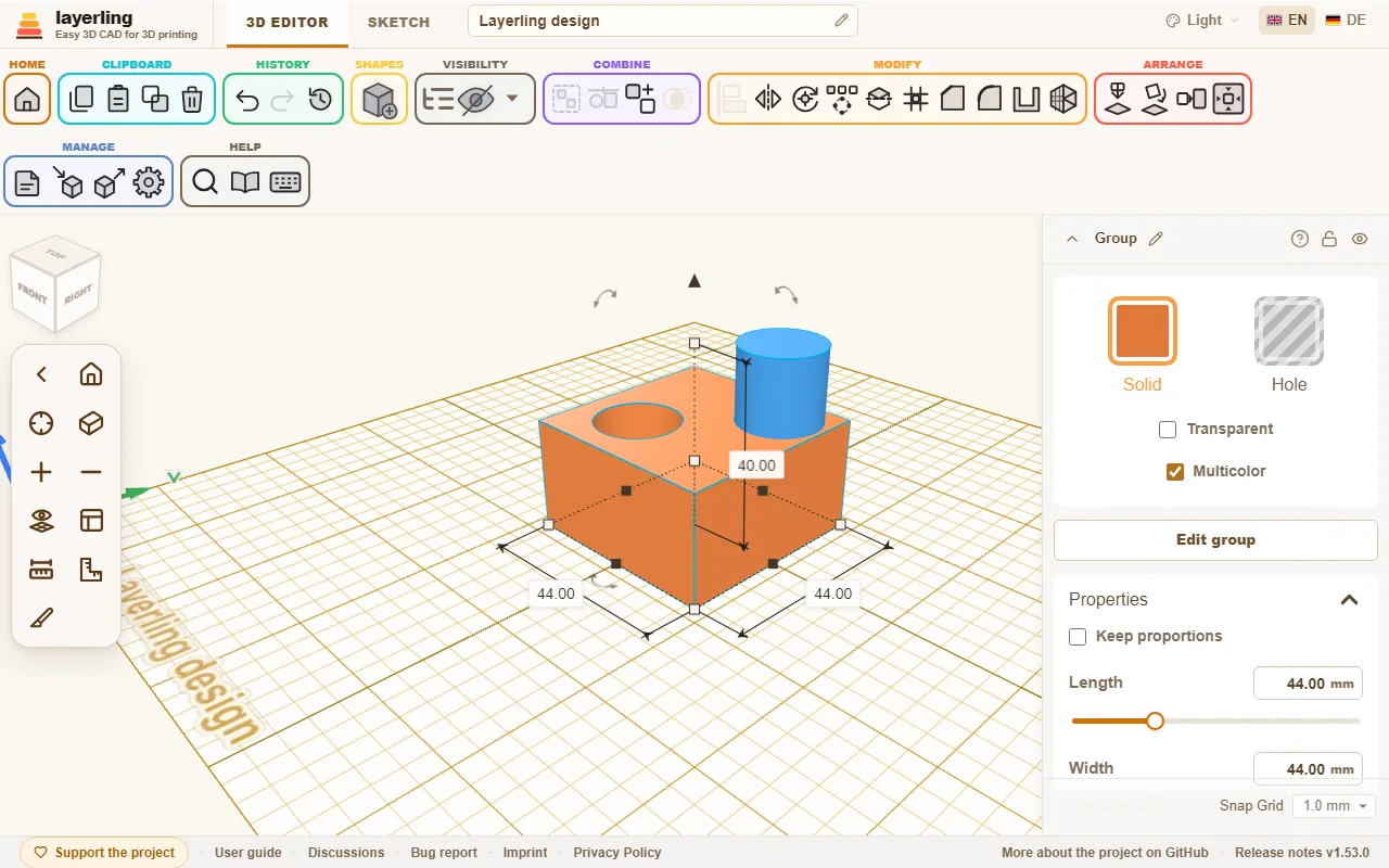
As soon as a shape is selected, its settings appear on the right. At the top is the name; the pencil beside it (“Rename”) lets you type a new one. Enter keeps it, Esc cancels, and an empty name brings back the shape's default name. Further right, the padlock locks the shape against accidental moving and the eye hides it. The arrow on the far left folds the settings down to their title bar.
The settings sit docked at the right edge. If they cover something you want to see, drag them by their title bar and they float wherever you drop them; they stay there for the next shape too. Drop them back at the top right, or double-click the title bar, and they dock again. While they float or are folded down, the snap step moves from the bottom of the settings to the bottom right of the workplane.

- “Solid” or “Hole”: A solid stays, a hole takes material away. A click on “Solid” opens the colours; colours of your own that you mix there wait under “Recently used” afterwards, the last eight. More in Solids and holes.
- “Transparent”: Lets you see through the body, for example to spot a shape behind it.
- “Multicolor”: For a group only. Switched on, every part of the group shows in its own colour, also in a group that was cut with holes into one body (the walls a hole leaves take the colour of the body they were cut into). Picking a colour for the group switches it off and colours the whole group. Bundles always keep their parts' colours. In a 3MF export every part keeps its colour, so the slicer can map the parts onto filaments; OBJ carries the colours on its points, so the border between two colours is a little rougher there.
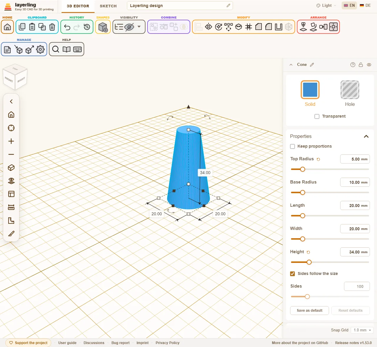
- “Properties”: The dimensions and everything that belongs to this shape. For a cylinder the diameter, the height and the number of sides. For a gear the teeth, for a spring the turns. A value you have moved away from its default gets a small arrow next to its name: a click takes just that value back, whatever else you did since, unlike Undo. Dragged with the mouse, the slider of a length snaps to the snap step, so a height comes out in whole millimetres (not with the grid off, and not on short sliders); a typed value and the arrow keys on the slider stay exact. “Save as default” at the bottom makes the current values the start values of this kind of shape (the same as “Shape defaults” in the settings), and “Reset defaults” goes back to the app's own.
- “Taper”: Different sizes at the top and bottom, for example for a slope or a funnel.
- “Twist & Lean”: Twists the top against the bottom or shifts it sideways. That gives twisted columns and leaning towers.
Taper and twist work on almost every shape. Only the gear, thread, spring, knurl, hinge, pyramid, bent tube, teardrop, the screw-head cutters and the ruler leave them out: they have fixed measures of their own or, like the pyramid, a top of their own already.
A tapered or leaning box, cylinder, ellipse, polygon, tube or ring keeps its exact shape, and so do the capsule, star, heart, crescent, dovetail and a rounded box without rounded top and bottom edges: chamfers and fillets work on it as on the plain shape, and the STEP export writes it. The same holds for a twisted shape: its section turns exactly as it rises, and the sides wind evenly from bottom to top.
Typing is more exact than dragging. All number fields take millimetres, but also percentages: type "50 %" into a width of 40 mm and you get 20 mm. They calculate too: "15*3", "120-2*4" or "(40+2)/2" give 45, 112 and 21; x works instead of *. The field remembers the calculation, in the Properties panel as well as in the dimension boxes around the selected body: click into it again later and the formula stands there instead of the number, as long as the value still matches it, and you change it in place, "(140+2)/2" becoming "(40+6)/2". Drag the body by a handle or scale it and the formula no longer fits, so the field shows just the number again.
How round is round? The side count
Round shapes such as cylinder, cone, tube, ellipse or the bores have the switch “Sides follow the size” and the slider “Sides” in their properties. The “Torus” has two sliders: “Ring sides” around the ring and “Tube steps” around the tube. They follow the size there too until you hold them, so a large torus shows no facets. The reason: for the view and for STL, 3MF and OBJ, layerling draws a circle as a polygon of many small sides. The more sides, the smoother it is, and the more triangles it takes.
Where the side count matters
- In the export for the slicer (STL, 3MF, OBJ). A cylinder with few sides arrives there as a polygon.
- When bodies and holes are combined. A bore cut by a hole with few sides is angular in the finished part. That includes screw holes.
- In the view. Many very fine shapes slow the editor down.
Where it does not matter
- For the STEP export. It writes the round shape, not the polygon.
- For chamfers and fillets (“Chamfer”, “Fillet”) as long as the shape stays round. That is the case when you have not set a side count, when the count is at least the shape's default, or when the polygon strays at most 0.05 mm from the circle. The default is 96 sides for cylinder, ellipse, tube and cone, 64 for the “Round Roof”, 24 steps for the “Sphere”, 32 for the “Half Sphere”, 96 sides and 24 steps for the “Torus”, and a “Quality” of 32 for a round “Bent Tube”.
- For a thread, a spring or a helical gear. The edge tool and the STEP export take its exact body; its “Quality” only sets how finely it is drawn.
Where it matters again
- For chamfers and fillets on a shape with few sides. If you set the side count below the default, the edge tool takes the shape as it is drawn: a cylinder with 6 sides stays a hexagonal bar, and the fillet runs round its six edges. That is how you can build, for instance, a nut pocket with rounded corners. For a round shape, leave “Sides follow the size” on.
How to use it
- Leave “Sides follow the size” on. Then layerling picks the side count from the diameter so that the polygon strays at most 0.005 mm from the true circle, far below what a printer resolves. Small shapes get at least 24 sides, large ones more.
- Fewer sides you take when you want a polygon on purpose (but there is the “Polygon” for that) or when the editor gets slow with very many round shapes.
- More sides you hardly ever need. Only on very large round parts, when you see edges in the STL.
- For parts you only treat with edges or hand on as STEP, the side count does not matter.
Working with the handles
Besides the settings there are handles on the shape itself:
- The corners and edges make the shape larger or smaller. Hold Shift while dragging a corner to scale width, depth and height together and keep the proportions; hold Alt to scale from the center instead of the opposite corner. Without a keyboard, or if you do not want to hold a key, switch on “Keep proportions” at the top of the properties: then the corners always keep the proportions, and typing one of width, depth or height scales the other two by the same factor. The setting is remembered.
- The arrow on top changes the height, the handle in the middle lifts or lowers the shape.
- The curved arrows rotate it.
- The numbers beside the shape show the dimensions. A click on one opens a field in which you type the number you want.
- A click on a corner (without dragging) opens width and depth together. Type the first, press Tab for the second and Enter to apply both. Esc cancels.
Once a shape is turned by right angles, for instance laid on its side with “Lay flat on face”, the fields in the properties are named after the direction each measure runs in now: “Height” is what goes up, “Width” runs along X and “Length” along Y. Typing the height of a shape lying down therefore changes the vertical measure, and its underside stays on the plate. A shape tilted at any other angle shows its own measures in the fields, and a note below says so.
Without the mouse, use the keyboard: the arrow keys move the selection by one snap step (0.1 mm when the grid is off), with Shift by five, or by ten if you set “Darker grid line every” to 10 “{count} grid steps” in the settings under “Appearance”: as far as the next darker line, as in Tinkercad. They follow the view: → moves to where the screen's right is, ↑ away from you, even after turning the plate. Push a shape out of the picture and the view moves along. Ctrl+↑ and Ctrl+↓ raise and lower it. R rotates by 45°, Shift+R by 22.5°. D drops the selection onto the workplane.
The handles pull a shape as large as your plate, at least 220 mm wide and deep. Typing a number in the properties goes beyond that, and a shape made that large does not shrink back when you grab it again. A ceiling of your own per shape is set in the settings under “Shape defaults” with “Custom size limit”.
The snap step is at the bottom right of the editor and can be changed at any time.
Copying and duplicating
“Copy”, “Paste” and “Duplicate” are in the ribbon (“Clipboard”). Ctrl+D duplicates a selection. layerling remembers how you last moved or rotated the copy and applies the same again on the next duplicate. That produces a row of holes or steps in a few key presses. For regular arrangements there is also the pattern, described in Selecting and arranging.
Custom shapes
A holder, a grip or a base plate you need again and again goes into the “Custom shapes”. They sit at the top of the shape library, above the “Basic shapes”, and fold away with their arrow.
- Select one or more bodies, holes, groups or an imported model included.
- Open the shape library and click “Save selection”. Enter a name and confirm with “Save”.
- In any design, a click on the tile inserts the shape, like any other shape. You can also drag the tile onto the workplane; it then lands where you let go.
Several bodies come back together, placed as they stood to each other, and stay selectable one by one. The pencil on a tile renames it, the bin removes it after asking. Shapes already inserted into designs stay as they are.
The “Custom shapes” live in this browser, apart from the designs, and are there again the next time you start. “Back up all” on the start page backs them up with the designs, and opening the backup brings both back. To take only the shapes to another browser, “Back up custom shapes” (the arrow pointing down) saves them as a ZIP file and “Load shapes” (the arrow pointing up) brings them back there. “Load shapes” also takes single .lyl designs; each one becomes a shape. Shapes already there are not added twice.
Custom shapes on the server
With the shared server store switched on, the section shows two groups: “On the server” and “In this browser”. When saving you choose where the shape goes; the server is chosen to start with. There it lives in the folder Custom shapes, as a .lyl file of its own with a picture, ready on every device that reaches the server. The cloud on a browser tile puts that shape on the server; it is then no longer kept twice.
The Custom shapes folder shows on the start page as well. Open a shape there like a design, change it, and it is saved automatically like any design on the server; the next insert takes the new version. As the server store has no login, everyone who reaches the server sees the same shapes.
Wrapping around a cylinder
Should a pattern, a logo or lettering go onto a cup, a can or a tube? First lay it flat on the plate, as an imported SVG or as text for example, the way it should look from above. Then wrap it around a cylinder in the shape's settings under “Wrap around a cylinder”:
- Open “Wrap around a cylinder” and enter the “Diameter” of the cylinder wall, such as the outside diameter of your cup. Tenths of a millimetre work too, such as 63.5.
- Click “Wrap”. What ran from left to right now runs around the cylinder, the back edge becomes the top, and the thickness stands out of the wall.
- Select the wrapped shape and the cylinder and centre both, left to right and front to back. The middle of the wrapped shape is the cylinder's axis, so it then sits right on its wall.
For an engraving, switch on “Inward (engraving)”: the thickness then goes into the wall. Make the shape a hole, centre it and group it with the cylinder.
The result is a mesh like an imported model. Undo lays the shape flat again; for another diameter, undo first and wrap again. It cannot go further than once around the cylinder; then layerling names the smallest diameter that fits.